Measuring Your Own Supply Voltage
13th April 2021
This article shows how to use the analogue-to-digital converter on the AVR DA-Series, AVR DB-Series, or ATtiny 0/1-Series microcontrollers, to measure and display the power supply voltage:
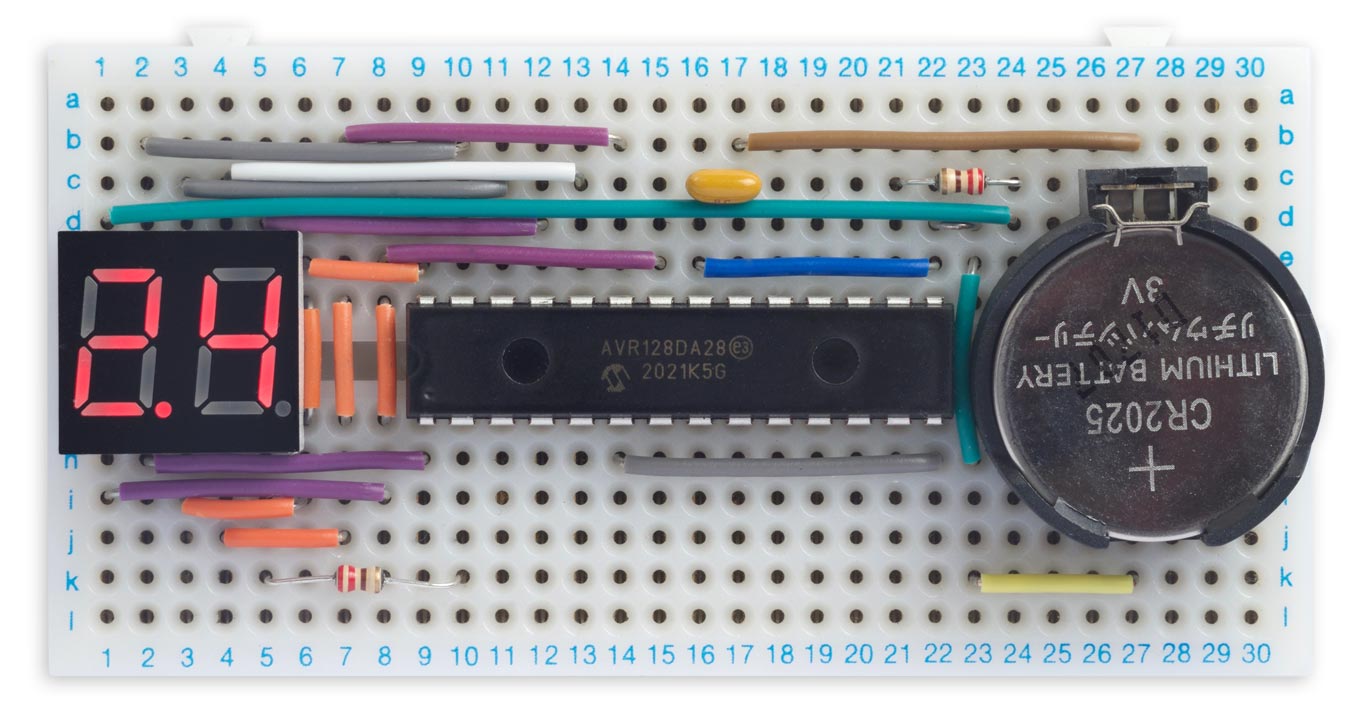
Displaying the power supply voltage on an AVR128DA28.
It's useful for monitoring a microcontroller-based project which uses a supply that might vary, such as a battery, solar cell, or energy harvester, so you can display the battery voltage to the user, or monitor it so you can take action when it drops too low.
I've included example code for each family, as the approach is slightly different in each case.
Introduction
This exercise started when I recently wanted to display the battery voltage for another project I'm working on, using the on-board analogue-to-digital converter to minimise the need for additional components. Most AVR chips allow you to do this, but it turns out that the technique isn't always as straightforward as you might think.
There is an established 'backwards' technique for doing this on the older ATtiny and ATmega chips:
- Set the ADC reference to VCC (or VDD [1]).
- Set the ADC MUX to read the smallest available reference voltage; eg 1.1V.
- Read the ADC.
You can then work backwards to work out what VCC is based on the reading you get.
For example, if the 10-bit reading is 512, ie 50% of full scale, then your 1.1V reference is 50% of VCC and VCC is therefore 2.2V.
The reason for choosing the smallest available reference voltage is that it will determine the lowest supply voltage you'll be able to read.
Measuring VDD on an AVR128DA28
With the DA series things are a bit complicated, and I had to do some experimentation to work out what was going on because it isn't fully explained in the datasheet.
The ADC.MUXPOS register on the AVR128DA28 let's you choose to read one of three voltage reference options: DACREF0, DACREF1, and DACREF2.
It turns out that these are generated by the AC (Analog Comparator) peripheral. DACREFn is:
where VREF.ACREF is the single Analog Comparator voltage reference, which is shared between all three Analog Comparators, and ACn.DACREF is a byte stored in the DACREF register for Analog Comparator n which sets a voltage divider.
The ACn.DACREF values all default to 255, so DACREF0, DACREF1, and DACREF2 are initially all 255/256 times the Analog Comparator shared VREF setting. Note that the 255/256 factor is significant. It makes the default voltage references from DACREF0, DACREF1, and DACREF2 1.02V rather than the 1.024V you might expect.
Setting up the ADC
The procedure to set up the ADC is:
- Set the ADC's voltage reference to 1.024V.
- Set the Analog Comparator's shared voltage reference to VDD.
- Set Analog Comparator 0's DACREF value to 32.
- Set the ADC MUXPOS so the ADC measures DACREF0.
Here's the code to implement this:
void ADCSetup () {
  VREF.ADC0REF = VREF_REFSEL_1V024_gc;
  VREF.ACREF = VREF_REFSEL_VDD_gc;
  AC0.DACREF = 32;                                     // Maximum DACREF0 voltage
  ADC0.MUXPOS = ADC_MUXPOS_DACREF0_gc;                 // Measure DACREF0
  ADC0.CTRLC = ADC_PRESC_DIV64_gc;                     // 375kHz clock
  ADC0.CTRLA = ADC_ENABLE_bm;                          // Single, 12-bit
}
The datasheet specifies that the ADC clock should be at least 150kHz, so I've chosen a divider of 64 which gives a clock of 375kHz with a 24MHz processor clock.
Reading the voltage
Here's the routine to measure the supply voltage:
void MeasureVoltage () {
  ADC0.COMMAND = ADC_STCONV_bm;                        // Start conversion
  while (ADC0.COMMAND & ADC_STCONV_bm);                // Wait for completion
  uint16_t adc_reading = ADC0.RES;                     // ADC conversion result
  uint16_t voltage = adc_reading/50;
  Buffer[0] = voltage/10; Buffer[1]= voltage%10;
}
The ADC is now measuring 32/256 or 1/8 of VDD, which will always be within range of the 1.024 voltage reference.
The calculation is:
So:
To get VDD in tenths of a volt we therefore need to divide the ADC reading by 50.
The maximum voltage we can measure this way is 4095/500 or 8.19V, which is well above the maximum supply voltage of 5.5V.
Note that you can also use the same 'backwards' technique as on the older ATmega and ATtiny chips, although I can't think of any advantage; if you're interested see Measuring Your Own Supply Voltage 2.
Measuring VDD on an AVR128DB28
The AVR128DB28 is significantly different from the AVR128DA28 in the areas of the AC, VREF, and ADC. There are separate voltage references for each instance of the Analog Comparator, and there is no DACREF voltage divider. Instead there is an option to use the ADC to read VDD/10, which makes measuring the supply voltage particularly simple.
Setting up the ADC
The procedure to set up the ADC is:
- Set the ADC's voltage reference to 1.024V.
- Set the ADC MUXPOS so the ADC measures VDD/10.
Here's the code to implement this:
void ADCSetup () {
  VREF.ADC0REF = VREF_REFSEL_1V024_gc;
  ADC0.MUXPOS = ADC_MUXPOS_VDDDIV10_gc;                // VDD/10
  ADC0.CTRLA = ADC_ENABLE_bm;                          // Single, 12-bit
}
The datasheet specifies that the ADC clock should be at least 125kHz, so I've chosen a divider of 64 which gives a clock of 375kHz with a 24MHz processor clock.
Reading the voltage
Here's the routine to measure the supply voltage:
void MeasureVoltage () {
  ADC0.COMMAND = ADC_STCONV_bm;                        // Start conversion
  while (ADC0.COMMAND & ADC_STCONV_bm);                // Wait for completion
  uint16_t adc_reading = ADC0.RES;                     // ADC conversion result
  uint16_t voltage = adc_reading/40;
  Buffer[0] = voltage/10; Buffer[1]= voltage%10;
}
The calculation is:
So:
To get VDD in tenths of a volt we therefore need to divide the ADC reading by 40.
The maximum voltage we can measure this way is 4095/400 or 10.2V, which is well above the maximum supply voltage of 5.5V.
Measuring VDD on the ATtiny 0-Series and 1-Series
Unlike the AVR DA- and DB-Series, the ATtiny 0-Series and 1-Series microcontrollers don't provide a VDD option in the VREF (Voltage Reference) peripheral, but the ADC provides an option in the CTRLC register that allows you to choose between the internal reference set by VREF and VDD, so we can use the same 'backwards' technique as for the old ATtiny and ATmega chips.
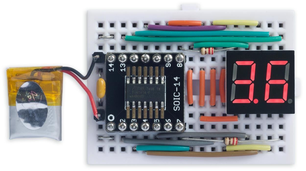
Displaying the power supply voltage on an ATtiny414.
Setting up the ADC
The procedure to set up the ADC is:
- Set the VREF peripheral to generate an internal reference for the ADC of 1.1V.
- Set the ADC to use VDD as the voltage reference.
- Set the ADC MUXPOS to read the internal reference voltage generated by the VREF peripheral.
Here's the code to implement this:
void ADCSetup () {
  VREF.CTRLA = VREF_ADC0REFSEL_1V1_gc;
  ADC0.CTRLC = ADC_REFSEL_VDDREF_gc | ADC_PRESC_DIV256_gc; // 78kHz clock
  ADC0.MUXPOS = ADC_MUXPOS_INTREF_gc;                  // Measure INTREF
  ADC0.CTRLA = ADC_ENABLE_bm;                          // Single, 10-bit
}
The datasheet specifies that the ADC clock should be between 50kHz and 1.5MHz, so I've chosen a divider of 256 which gives a clock of 78kHz with a 20MHz processor clock.
Here's the routine to measure the supply voltage:
void MeasureVoltage () {
  ADC0.COMMAND = ADC_STCONV_bm;                        // Start conversion
  while (ADC0.COMMAND & ADC_STCONV_bm);                // Wait for completion
  uint16_t adc_reading = ADC0.RES;                     // ADC conversion result
  uint16_t voltage = 11264/adc_reading;
  Buffer[0] = voltage/10; Buffer[1]= voltage%10;
}
The calculation is as follows. Suppose we have a 10-bit reading of R. Then:
which gives:
To get VDD in tenths of a volt we therefore need to divide 11264 by the ADC reading.
The minimum voltage we can measure this way is 1126.4/1023 or 1.1V, which is below the minimum supply voltage of 1.8V.
The circuit
Here are the circuits I used to test these routines:
AVR DA/DB-Series version
Circuit used to display the power supply voltage on an AVR128DA28.
I used a two-digit common-cathode 7-segment LED display. The segments are driven by PA0 to PA7. Two spare pins are used to drive the digits, PF0 and PC0, via current-limiting resistors.
I used SPDIP versions of the AVR128DA28 or AVR128DB28, because they are convenient to connect up on a breadboard, but the same approach could probably be used with any member of the DA- or DB-series.
ATtiny 0/1-Series version
Circuit used to display the power supply voltage on an ATtiny414.
I used the same two-digit common-cathode 7-segment LED display. The segments are driven by PB0 and PA1 to PA7. PB1 and PB2 are used to drive the digits via current-limiting resistors.
I mounted the ATtiny414 on a breakout board so I could use it on a breadboard [2]. The program and circuit is probably suitable for any 14-pin member of the ATtiny 0/1-Series.
The program
The rest of the program is similar between the versions for the AVR DA/DB-Series, and the ATtiny 0/1-Series. The following listings show the AVR DA/DB-Series version:
The routine TCASetup() configures Timer/Counter TCA0 to generate a 125Hz interrupt:
void TCASetup () {
  TCA0.SINGLE.INTCTRL = TCA_SINGLE_OVF_bm;             // Enable interrupt
  TCA0.SINGLE.CTRLB = TCA_SINGLE_WGMODE_NORMAL_gc;     // Set Normal mode
  TCA0.SINGLE.PER = 2999;                              // Set the period -> 125Hz
  TCA0.SINGLE.CTRLA = TCA_SINGLE_CLKSEL_DIV64_gc;      // Clock divided by 64
  TCA0.SINGLE.CTRLA = TCA0.SINGLE.CTRLA | TCA_SINGLE_ENABLE_bm; // Enable
}
The interrupt service routine multiplexes the display, and samples and displays the voltage once a second:
ISR(TCA0_OVF_vect) {
  TCA0.SINGLE.INTFLAGS = TCA_SINGLE_OVF_bm;            // Clear interrupt
  DisplayNextDigit();
  Ticks++;
  if (Ticks == Second) {
    Ticks = 0;
    MeasureVoltage();
  }
}
The number to display on each digit is put into the array Buffer[] by the MeasureVoltage() routine. DisplayNextDigit() copies the appropriate segment pattern for the current digit to PORTA, and takes the digit line low to display the digit:
void DisplayNextDigit() {
  static uint8_t digit = 0;
  digit = 1 - digit;                                   // Toggle digits 0 and 1
  uint8_t segs = Char[Buffer[digit]];                  // Segments
  if (digit == 0) segs = segs | 0x80;                  // Decimal point
  PORTA.OUT = segs;                                    // Take segments high
  if (digit == 1) {                                    // Take digit low
    PORTC.OUTCLR = PIN0_bm;
    PORTF.OUTSET = PIN0_bm;
  } else {
    PORTC.OUTSET = PIN0_bm;
    PORTF.OUTCLR = PIN0_bm;
  }
}
The whole routine runs under interrupt, so nothing needs to be done in loop().
Compiling the program
ATtiny 0/1-Series version
Compile the program using Spence Konde's megaTiny Core on GitHub. Choose the ATtiny1614/1604/814/804/441/404/241/204 option under the megaTinyCore heading on the Board menu. Check that the subsequent options are set as follows (ignore any other options):
Chip: "ATtiny414"
Clock: "20 MHz Internal"
Then upload the program to the ATtiny414 using a UPDI programmer. The megaTinyCore now supports the following two options:
- Make a UPDI programmer from an Arduino Uno, or other ATmega328P-based board, as described in Make UPDI Programmer, and set the Programmer option to "jtag2updi".
- Use a USB to Serial board, such as the SparkFun FTDI Basic board [3], connect TX to the UPDI pin via a 4.7kΩ resistor, connect RX directly to the UPDI pin, and set the Programmer option to "Serial port and 4.7k (pyupdi style)".
You can ignore the error "Cannot locate flash and boot memories in description".
AVR DA/DB-Series version
Compile the programs using Spence Konde's Dx Core on GitHub. Choose the AVR DA-series (no bootloader) or AVR DB-series (no bootloader) option under the DxCore heading on the Board menu. Check that the subsequent options are set as follows (ignore any other options):
Chip: "AVR128DA28" or "AVR128DB28"
Clock Speed: "24 MHz internal"
Then upload the program to the processor on the breadboard using one of the two UPDI programmer options as described above for the ATtiny 0/1-Series version.
Resources
Here's the whole AVR DA/DB-Series version of the Supply Voltage Display program: Supply Voltage Display AVR DA/DB Version.
And here's the whole ATtiny0/1-Series version of the Supply Voltage Display program: Supply Voltage Display ATtiny Version.
Thanks to Spence Konde, without whose help I wouldn't have been able to figure out how to get these techniques to work.
- ^ Atmel used to refer to the positive supply as VCC on their datasheets, but this is strictly incorrect because they are CMOS devices, which don't have Collectors (VCC) but Drains (VDD). This has been corrected to VDD on their recent datasheets.
- ^ SMT Breakout PCB for SOIC-14 or TSSOP-14 on Adafruit.
- ^ SparkFun FTDI Basic Breakout - 5V on Sparkfun.
blog comments powered by Disqus