Tiny Thermocouple Thermometer
5th March 2019
This project describes a thermocouple thermometer, capable of measuring temperatures up to +1350°C, using just an ATtiny85 and an OLED display:
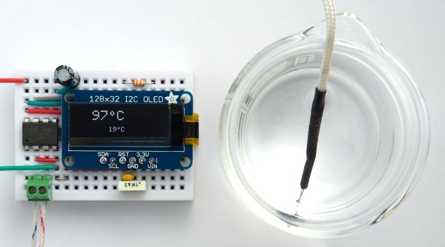
Thermocouple thermometer based on an ATtiny85 measuring boiling water.
It uses the ATtiny85's analogue-to-digital converter with a x20 gain option to measure the thermocouple voltage, and the internal temperature sensor to measure the ambient temperature (shown on the bottom line of the display), and it gives readings accurate to better than 5°C. Some possible applications include a cooking thermometer, a soldering-iron temperature monitor, or a wood burning stove temperature display.
Introduction
I've recently wanted to build a circuit capable of measuring temperatures around 250°C, and so the temperature sensors I’ve used in previous projects, such as the DS12B20, aren't suitable because they usually have an upper temperature limit of 150°C. The sensor of choice here is a thermocouple, which uses the fact that a junction between two different metals generates a small voltage proportional to temperature. The most common type of thermocouple, called the K type, uses chromel (a nickel-chromium alloy) and aluminel (a nickel/aluminium/manganese/silicon alloy).
One can use a custom thermocouple amplifier to translate the small voltage to a digital signal that you can read from a microcontroller; a popular choice is the MAX31855K which provides an SPI output [1].
However, it occurred to me that you could simply read the thermocouple directly using the analogue input on an ATtiny85. The ATtiny85 conveniently provides a 10-bit differential analogue input with a x20 gain option. A K-type thermocouple generates about 41µV/°C, so using the 1.1V voltage reference we can calculate the resolution and maximum range as follows:
- Resolution = 1.1/(1024 x 20 x 41 x 10-6) = 1.31°C
- Maximum = 1024 x 1.31 = 1341°C.
With oversampling one could get the resolution below 1°C which is definitely enough precision for many applications.
The ATtiny85 is one of a small number of AVR microcontrollers that include a gain option on the ADC inputs; the only others I know of are the ATtiny861, ATtiny167, and ATmega1284P.
Although K-type thermocouples will measure temperatures down to -200°C, for simplicity in this project I have only supported temperatures above room temperature. I may extend this in a future project if there's any interest.
Getting the temperature
How do you get the temperature from a measurement of the thermoelectric voltage?
The simplest way is to assume that the relationship between voltage and temperature is linear at 41µV/°C. For small temperature ranges this is a good approximation; however, over larger ranges there is a significant deviation from linear behaviour [2].
For maximum accuracy you can solve a ninth-order polynomial, using coefficients provided by the National Institute of Standards and Technology (NIST) [3]. However, this approach isn't necessary for the sort of accuracy I was aiming for.
The approach I used is a piece-wise linear model, approximating the standard response curve with a series of straight line segments. I looked up the temperatures for a series of fixed points, corresponding to ADC readings that are multiples of 128, using an online thermocouple temperature calculator [4]:
| ADC value | Voltage (mV) | Temperature (°C) |
| 0 | 0 | 0 |
| 128 | 6.875 | 168.36 |
| 256 | 13.750 | 337.02 |
| 384 | 20.625 | 499.55 |
| 512 | 27.500 | 661.26 |
| 640 | 34.375 | 826.91 |
| 768 | 41.250 | 999.34 |
| 896 | 48.125 | 1180.53 |
| 1024 | 55.000 | 1375.09 |
These were then coded as the following array of fixed points, in tenths of a degree, for linear interpolation of the temperature:
int Temperature[9] = { 0, 1684, 3370, 4995, 6613, 8269, 9993, 11805, 13751 };
The cold junction
The voltage generated by a thermocouple doesn't give you the absolute temperature, but the difference between the temperature of the probe and the temperature of the connection between the thermocouple and your circuit. This is traditionally referred to as the "cold junction" (even though if you're measuring subzero temperatures it will actually be warmer than the probe). All thermocouple amplifiers therefore incorporate a sensor to measure their internal temperature.
Fortunately the ATtiny85 includes an internal temperature sensor, so the thermocouple thermometer uses this to calculate the cold junction temperature.
The circuit
Here's the circuit:
Circuit of the thermocouple thermometer, based on an ATtiny85.
For the display I chose the I2C 128x32 OLED display available from Adafruit [5] or Pimoroni in the UK [6]. The 33kΩ resistor and 0.1µF capacitor ensure that the display is reset correctly when power is first applied, although you may not need them. Alternatively you could use an equivalent display from AliExpress [7], or an I2C 64x32 OLED display.
I used a K-Type thermocouple bought from eBay [8], but a wide range of probes is available from different suppliers.
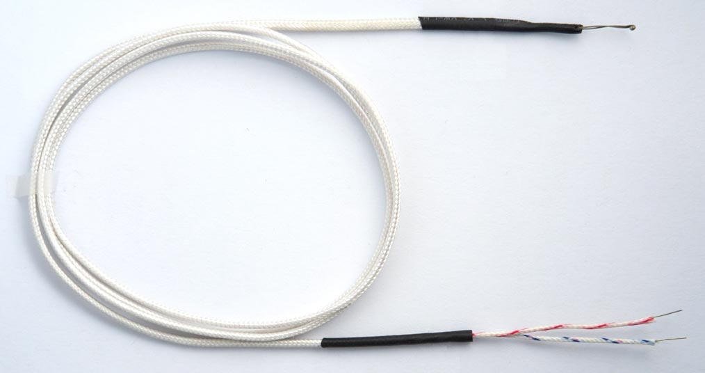
A typical K-Type thermocouple probe.
The program
For both the internal temperature measurement and the differential voltage measurement I do the analogue-to-digital conversions in sleep mode, as recommended by the datasheet to minimise noise from the processor and peripherals.
Driving the display
The display code is similar to the code I used in earlier projects that used the same 128x32 I2C OLED display, such as Tiny Machine-Code Monitor. In this project I only needed character-set definitions for the digits 0 to 9, and a few extra characters such as "-", "C", and a degree symbol.
The program allows you to plot double-sized characters; for details of how this works see Big Text for Little Display.
Measuring the internal temperature
The routine to set up the ADC for the internal temperature measurement is:
void SetupInternal () {
  ADMUX = 0<<REFS2 | 2<<REFS0 | 15<<MUX0;  // Temperature and 1.1V reference
  ADCSRA = 1<<ADEN | 1<<ADIE | 4<<ADPS0;   // Enable ADC, interrupt, 62.5kHz clock
  ADCSRB = 0<<ADTS0;                       // Free running
  set_sleep_mode(SLEEP_MODE_ADC);
}
The ReadInternal() routine takes a reading; it simply puts the processor to sleep. The ADC generates an interrupt to wake up the processor when the conversion is finished, and the routine then reads and returns the ADC register value:
unsigned int ReadInternal () {
  sleep_enable();
  sleep_cpu();                             // Start in ADC noise reduction mode
  return ADC;
}
Measuring the thermocouple voltage
A similar routine sets up the ADC for the thermocouple measurement:
void SetupThermocouple () {
  ADMUX = 0<<REFS2 | 2<<REFS0 | 7<<MUX0;   // PB4 (ADC2) +, PB3 (ADC3) was 7
  ADCSRA = 1<<ADEN | 1<<ADIE | 4<<ADPS0;   // Enable ADC, interrupt, 62.5kHz clock
  ADCSRB = 0<<ADTS0;                       // Free running
  set_sleep_mode(SLEEP_MODE_ADC);
}
The routine ReadThermocouple() actually takes the reading:
unsigned int ReadThermocouple () {
  sleep_enable();
  sleep_cpu();                             // Start in ADC noise reduction mode
  return ADC;
}
Converting the thermoelectric voltage to a temperature
The ADC reading from ReadThermocouple() is converted to a temperature using piece-wise linear interpolation, as described in Getting the temperature above. For greater accuracy I used the sum of four successive ADC readings; the routine Convert() takes this value and uses the values in the array Temperature[] to convert it to a temperature, in degrees:
int Temperature[9] = { 0, 1684, 3370, 4995, 6613, 8269, 9993, 11805, 13751 };

int Convert (int adc) {
  int n = adc>>9;
  unsigned int difference = Temperature[n+1] - Temperature[n];
  unsigned int proportion = adc - (n<<9);
  unsigned int extra = ((unsigned long)proportion * difference)>>9;
  return (Temperature[n] + extra + 5)/10;
}
If the parameter to Convert() is an exact multiple n of 512 the temperature is Temperature[n]/10. Otherwise the temperature is interpolated between Temperature[n] and Temperature[n+1].
Displaying the readings
Finally, the main loop in loop() reads the internal temperature and thermocouple temperature every second, and displays the readings on the display. For each measurement I take the average of 16 successive readings, to reduce the noise:
  SetupThermocouple();
  ReadThermocouple();                      // Throw away first reading
  int reading = 0;
  for (int i=0; i<16; i++) reading = reading + ReadThermocouple();
  reading = Convert(max((reading>>2) + ADCOffset*4, 0));
  Scale = 2;
  PlotTemperature(reading + internal, 0, 0);
Improving accuracy
There are two factors that influence the accuracy of the thermometer, and you can calibrate each of these to improve the accuracy.
Internal temperature sensor
If the internal sensor is incorrect, all readings will be offset by this error. It's therefore a good idea to calibrate the sensor at room temperature against a known thermometer as follows:
- Check the internal temperature reading on the bottom line of the display.
- Set the constant InternalOffset in the program to the required adjustment to make this equal to the measured ambient temperature.
ADC offset
With no input on the x20 differential input there is usually a small offset, which is added to every reading. To measure this:
- Remove the thermocouple, and put a wire link between the two differential inputs, PB3 and PB4, to give a zero input.
- Note the difference between the thermocouple reading and the internal temperature reading.
- Set the constant ADCOffset in the program to the required correction to make this difference zero.
Testing
Note that before using the thermocouple thermometer in a critical application you should test it against known temperatures. I tested the thermometer against a commercial thermocouple thermometer with boiling water at 100°C, and with olive oil at 220°C, and the readings were within 5°C in each case.
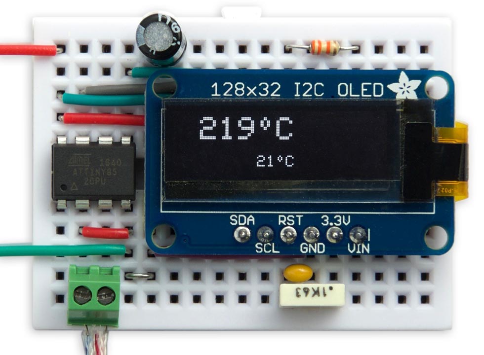
Thermocouple thermometer based on an ATtiny85.
To measure the temperature of a solid object you can attach the thermocouple to the object using polyimide tape, available from SparkFun [9] or Proto-PIC in the UK [10].
Compiling the program
I compiled the program using Spence Konde's ATTiny Core [11]. Choose the ATtiny25/45/85 option under the ATTinyCore heading on the Board menu. Then check that the subsequent options are set as follows (ignore any other options):
Chip: "ATtiny85"
Clock: "1 MHz (internal)"
B.O.D: "B.O.D. Disabled"
Timer 1 Clock: "CPU"
These are the default fuse settings for a new ATtiny85, but if you've previously used the ATtiny85 with different settings choose Burn Bootloader to set the fuses appropriately.
Then upload the program using ISP (in-system programming); I used Sparkfun's Tiny AVR Programmer Board; see ATtiny-Based Beginner's Kit.
Here's the Tiny Thermocouple Thermometer program: Tiny Thermocouple Thermometer Program.
Update
To display the temperatures in degrees Fahrenheit change the calls to PlotTemperature() in loop() to:
PlotTemperature(internal*9/5+32, 3, 6);
and
PlotTemperature((reading + internal)*9/5+32, 0, 0);
You'll probably also want to change the character definition of the "C" to an "F" in the CharMap[][] table:
{ 0x7F, 0x09, 0x09, 0x09, 0x01, 0x00 }, // F- ^ Thermocouple amplifier MAX31855 breakout board on Adafruit.
- ^ Calibrating Thermocouple Sensors on mstarlabs.com.
- ^ Inverse coefficients for K type thermocouple on NIST.
- ^ Thermocouple Voltage to Temperature Calculator on Fluke.
- ^ Monochrome 128x32 I2C OLED graphic display on Adafruit.
- ^ Adafruit Monochrome 128x32 OLED graphic display on Pimoroni.
- ^ 0.91 inch 128x32 I2C IIC Serial OLED LCD Display Module on AliExpress.
- ^ 1M K-Type Multimeter Temperature Thermocouple Probe on eBay.
- ^ High Temperature Adhesive Tape on SparkFun.
- ^ High Temperature Adhesive Tape on Proto-PIC.
- ^ ATTinyCore on GitHub.
blog comments powered by Disqus