16 LEDs Puzzle
4th December 2021
This project is a logic puzzle for the festive season. When you first connect power the puzzle displays a random pattern of LEDs. The aim is to press the buttons so that all the LEDs are turned on:
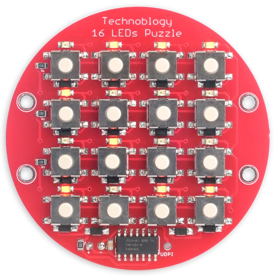
The 16 LEDs Puzzle, in which you have to press the buttons to light up all the LEDs.
It consists of 16 LEDs, 16 buttons, and an ATtiny404 (or ATtiny204) processor. Each button toggles the state of the LED above it, but it also has the side effect of toggling other LEDs on the matrix, so getting all the LEDs to turn on takes a bit of logical thinking. Note that you can solve the puzzle by pressing one button at a time; you don't need to press combinations.
As before, I'll give the solution in the first post of the New Year.
Introduction
I was trying to think of a good puzzle circuit to follow up last year's Five LEDs Puzzle, and chose this one based on a 4x4 matrix of buttons and LEDs. It's a simplified version of my Illuminated Button Matrix, redesigned to use low-cost push buttons and LEDs. You should be able to get the parts for around £6/$6, excluding the PCB and battery.
When you've succeeded in lighting all the LEDs they will all flash, and then a new random starting position will be displayed.
The circuit goes to sleep if you don't press any button for 30 seconds, to save power and avoid the need for an on/off switch. The total current consumption in sleep is about 1µA, so the drain on the battery in sleep is negligible. Press any key to wake the puzzle up again.
The circuit
There aren't any clues in the circuit. It simply connects the LEDs and buttons in a matrix, with four I/O lines used for the columns, and four for the rows:
Circuit of the 16 LEDs Puzzle, based on an ATtiny404.
To avoid the buttons shorting the LEDs when they are illuminated there needs to be a diode in series with each button. An alternative approach would be to use four additional I/O lines for the push button columns, but this would require 12 I/O lines, and the small 14-pin processors only provide 11. Small-signal diodes are less than 10p/10¢ each, so providing 16 of them isn't a big deal, and probably costs less than using a larger processor.
For the diodes I used BAV20W types as I already had a batch of them, but the popular 1N4148 are also suitable; see parts list below. For the LEDs I used low-cost orange LEDs that I bought in a pack a while ago, but any 0805 LEDs should be fine.
For the processor I decided to use one of the ATtiny range in a 14-pin SOIC package. The choice was between the older ATtiny84A (or ATtiny841), or the newer ATtiny404 or ATtiny414. I chose the newer range because they are substantially cheaper, and only need one wire for programming. Any of the range should be suitable, from the ATtiny204 to the ATtiny 1604 or from the ATtiny214 to the ATtiny1614, which is helpful as most of them seem to be in short supply at the moment. I used an ATtiny404, but I've linked to the ATtiny204 in the parts list because it's in stock at the time of writing. They are all software compatible, so the same program will work on any of them.
For the push buttons I used 6mm square surface-mount buttons. I got mine from Farnell (see parts list), but a similar button is available from AliExpress (choose the version with four feet) [1].
The circuit can be run from any suitable 3V to 5V supply, such as a 3.7V Lipo cell, or a pair of AAA batteries in series fitted into a suitable holder [2]. If you're using a Lipo cell I've designed the power connections so you can mount a through-hole JST socket on the reverse of the PCB to make it easy to connect the cell, or remove it for charging.
► Parts list
Construction
This circuit is a bit too complicated to build on a prototyping board so I decided to go straight to a PCB and use surface-mount components. I designed the board in Eagle and sent it to PCBWay for fabrication. I've included links at the end of the article so you can order yourself a board.
I used a Youyue 858D+ hot air gun at 275°C and Chip Quik SMD291AX10T3 solder paste to solder the SMD components onto the front of the board, but if you don't have a hot air gun or reflow oven you should be able to solder the SMD components with a bit of care using a fine-tipped soldering iron and fine solder, or solder paste. Most of the components are 0805 size, with a lead spacing of 1.65mm (0.065in). The component with the smallest spacing is the SOIC processor, which has a lead spacing of 1.27mm (0.05in) [3].
I tested the board after mounting all the components apart from the push buttons, and then once I was sure everything was correct, mounted the buttons using solder paste and a soldering iron. Finally I attached a Lipo battery on the back of the board with a removable double-sided sticky pad:
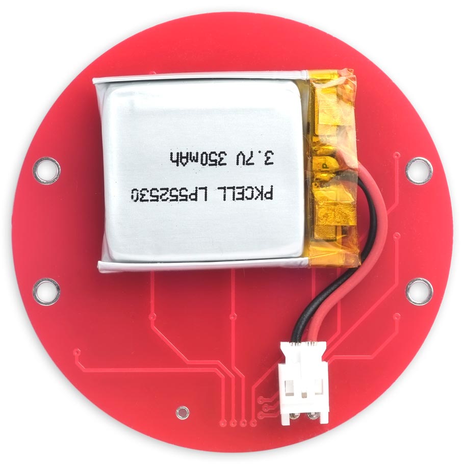
Back view of the 16 LEDs Puzzle PCB, showing the Lipo cell connected via a JST socket.
You can use a spare PCB as a back panel, held in place with four threaded pillars and M2.5 screws [4].
The program
The program works as follows:
- By default the column lines are defined as inputs.
- To light up the LED at the intersection of a row and column you take the column line high and the row line low.
- To test the state of a push button at the intersection of a row and column you take the column line low and make the row line an input with a pullup. If the button is pressed the input will be low.
The program scans the matrix a column at a time, first checking the state of the buttons on the four rows, and then setting the state of the LEDs on the four rows. The global variable Lights determines the state of the LEDs; bit 0 specifies the state of LED 0 on the above diagram, and so on. The variable Keys stores the state of the push buttons; again, bit 0 gives the state of button 0, and so on.
Timer
The key and LED matrix is multiplexed using Timer/Counter TCB to generate an interrupt at 250Hz, which is fast enough to avoid flicker. The Timer/Counter is set up by the routine TimerSetup():
void TimerSetup () {
  // Set up Timer/Counter TCB to multiplex the display
  TCB0.CCMP = (unsigned int)(F_CPU/250 - 1);          // Divide clock to give 250Hz
  TCB0.CTRLA = TCB_CLKSEL_CLKDIV1_gc | TCB_ENABLE_bm; // Enable timer, divide by 1
  TCB0.CTRLB = 0;                                     // Periodic Interrupt Mode
  TCB0.INTCTRL = TCB_CAPT_bm;                         // Enable interrupt
}
The interrupt service routine then clears the interrupt flag and calls DoNextColumn():
ISR(TCB0_INT_vect) {
  TCB0.INTFLAGS = TCB_CAPT_bm;                        // Clear the interrupt flag
  DoNextColumn();
}
Processing each column
The routine DoNextColumn() steps through four cycles, with the variable Cycle set to 0 to 3.
void DoNextColumn() {
  static unsigned int Keys, LastKeys = 0;
  static uint8_t Cycle;
  PORTB.OUT = 0x0F;                                   // Turn off previous LEDs
  Cycle = (Cycle + 1) & 0x03;
  uint8_t column = 1<<(Cycle+4);                      // Column 4 to 7
  PORTA.DIR = column;                                 // Make column output

  // Read keys in one column
  PORTA.OUT = 0;                                      // Make column low
  PORTB.DIR = 0;                                      // Make rows inputs
  Keys = Keys & ~(0x0F<<(Cycle*4)) | (~PORTB.IN & 0x0F)<<(Cycle*4);

  // Set lights in one column
  PORTA.OUT = column;                                 // Make column high
  uint8_t row = Lights>>(Cycle*4) & 0x0F;
  PORTB.DIR = row;                                    // Make active rows outputs
  PORTB.OUT = ~row;                                   // Copy row of lights to LEDs

  // Last cycle? Check Keys is stable
  if (Cycle == 3) {
    if (DeadTime != 0) {                              // Allow for key debounce
      DeadTime--;
    } else if (Keys != LastKeys) {                    // Change of state
      LastKeys = Keys;
      DeadTime = 10;
      if (Keys != 0) {
        Puzzle(Keys);
        Start = millis();                             // Delay sleep
      }
    }
  }
}
First it takes the appropriate column low and defines the four rows as inputs with pullups. It then reads the state of PB0 to PB3 to check if any of the buttons in that column are pressed. Over the four cycles the states of all 16 buttons are stored in the variable Keys.
It then takes the same column high and makes the rows outputs. It copies the appropriate four bits of Lights to PB0 to PB3 to define the state of the LEDs in that column.
After the end of the last cycle, when Cycle is 3, it checks whether the state of Keys has changed since LastKeys. To avoid the effects of key bounce there's a counter, DeadTime, which waits for 10 complete cycles of the routine before checking the keys again. Since DoNextColumn() is called by the 250Hz interrupt this is equivalent to a dead time of 160ms.
If one or more keys have been pressed the routine calls Puzzle(), and resets Start to the current time to reset the sleep counter.
Because of the multiplexing, each LED is only turned on for a proportion of the time. The total current consumption at 5V with all LEDs illuminated is about 43mA, which is well within the 200mA maximum specified for the ATtiny404.
The puzzle
The routine Puzzle() changes the state of Lights according to the rules of the puzzle:
void Puzzle (unsigned int keys) {
  unsigned int ne, nw, se, sw;
  ne = nw = se = sw = keys;
  for (int i=0; i<3; i++) {
    ne = (ne & 0x7777)>>3; keys = keys | ne;
    nw = (nw & 0xEEEE)>>5; keys = keys | nw;
    se = (se & 0x7777)<<5; keys = keys | se;
    sw = (sw & 0xEEEE)<<3; keys = keys | sw;
  }
  Lights = Lights ^ keys;
}
I won't explain how this works as that's part of the puzzle!
To test the board, and check all the soldered joints, you can define Puzzle() as:
void Puzzle (unsigned int keys) {
  Lights = Lights ^ keys;
}
This will simply toggle each light when you press the corresponding button.
The main program
The main program waits in a while loop for the Timeout period, repeatedly checking whether the puzzle has been solved:
void loop () {
  PORTA.DIR = 0x00;                                   // Make columns inputs
  SetRows(PORT_PULLUPEN_bm);                          // Turn on input pullups
  Start = millis();
  while (millis() - Start < Timeout) {                // Stay awake until timeout
    if (Lights == 0xFFFF) {                           // Solved puzzle?
      delay(1000);
      for (int n=0; n<4; n++) {
        Lights = ~Lights;
        delay(500);
      }
      Randomize();
    }
  }

  // Get ready to go to sleep
  PORTA.DIR = 0xF0;                                   // Make columns outputs
  PORTA.OUT = 0x00;                                   // Make columns low
  PORTB.DIR = 0;                                      // Make rows inputs
  SetRows(PORT_PULLUPEN_bm | PORT_ISC_LEVEL_gc);      // Add pin change interrupts
  sleep_cpu();                                        // Go to sleep
  DeadTime = 100;
}
If it has been solved, after a short delay the LEDs are flashed twice, and then a new random pattern is set on the grid.
If the timeout has been exceeded the rows are reprogrammed with pin change interrupts, and the processor is put to sleep to minimise the power consumption. Pressing any key generates a pin change interrupt which wakes the processor, and restores the previous pattern of lights.
Compiling the program
Compile the program using Spence Konde's megaTiny Core on GitHub. Choose the ATtiny3224/1624/1614/1604/824/814/804/424/414/404/241/204 option under the megaTinyCore heading on the Board menu. Check that the subsequent options are set as follows (ignore any other options):
Chip: "ATtiny404" (or "ATtiny204")
Clock: "20 MHz internal"
millis()/micros() Timer: "Enabled (default timer)"
Then upload the program to the ATtiny404 or ATtiny204 using a UPDI programmer. The recommended option is to use a USB to Serial board, such as the SparkFun FTDI Basic board [5], connected with a 4.7kΩ resistor as follows:
Then set the Programmer option to "SerialUPDI with 4.7k resistor or diode (230400 baud)".
Resources
Here's the 16 LEDs Puzzle program: 16 LEDs Puzzle Program.
Or get the program from GitHub, together with the Eagle files for the PCB so you can make yourself a board: https://github.com/technoblogy/16-leds-puzzle.
Or order boards from OSH Park here: 16 LEDs Puzzle.
Or order boards from PCBWay here: 16 LEDs Puzzle.
Updates
2nd January 2022: Updated the photograph of the back of the PCB to show a Lipo cell connected via a JST socket.
4th January 2022: Updated the program to solve a problem that occasionally caused the board to take longer to go to sleep. Also, added a suggestion about a back panel.
- ^ SMD Push Button Switches Red on AliExpress.
- ^ Keystone 2 AAA battery holder on Farnell.
- ^ Small outline integrated circuit on Wikipedia.
- ^ Black Nylon Screw and Stand-off Set – M2.5 Thread on The Pi Hut.
- ^ SparkFun FTDI Basic Breakout - 5V on Sparkfun.
blog comments powered by Disqus