Dot Matrix Clock
15th November 2015
This article describes a simple 12-hour clock using two dot-matrix displays to display the time, controlled by an ATtiny2313 processor:
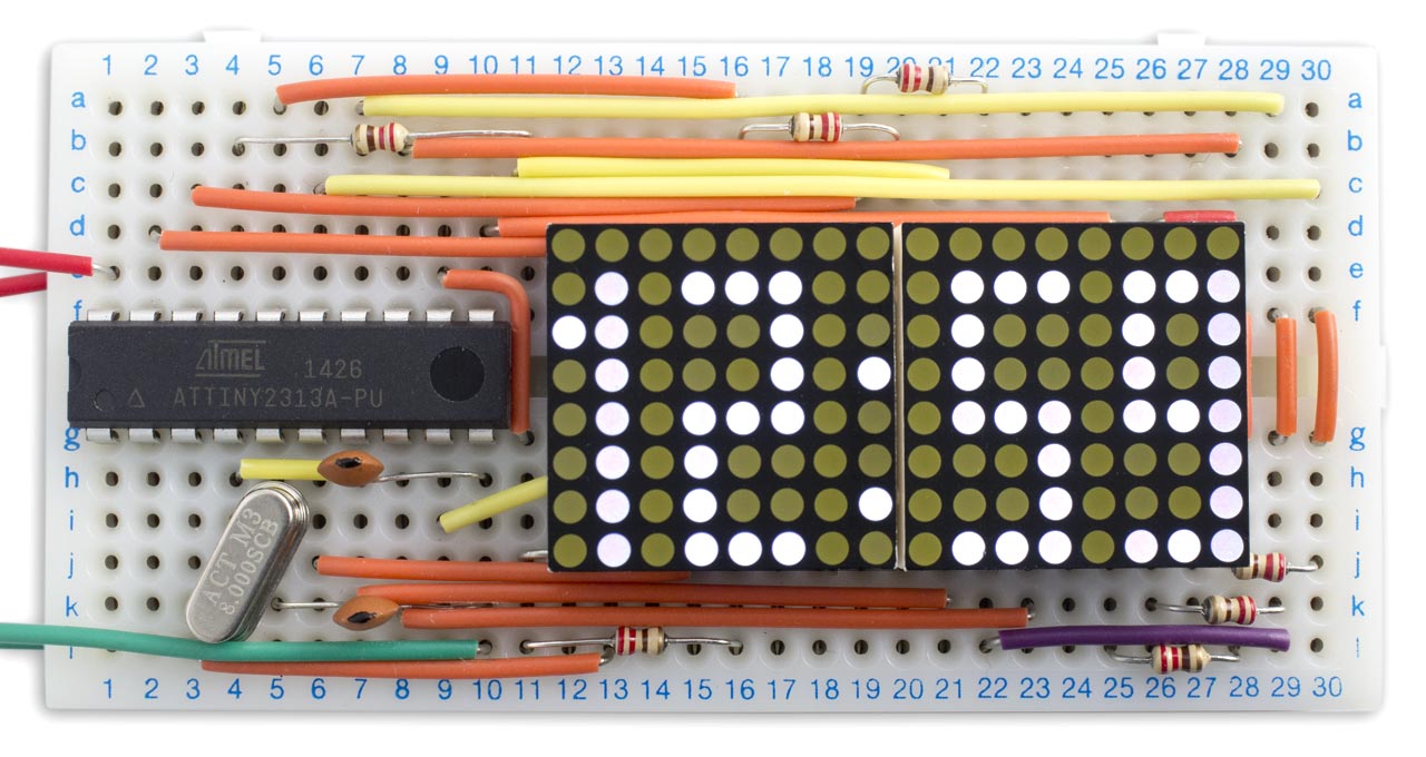
Dot matrix clock based on an ATtiny2313.
Introduction
I wanted to design myself a clock that was a bit more individual than one using a standard 7-segment display, so I decided to try basing one on a pair of 8x8 dot matrix LED displays. These are available fairly cheaply from a number of sources. I chose a pair of 0.8" 8x8 LED matrix displays from Adafruit [1]. They are available in a range of different colours, but I chose white because they tend to be the brightest, and this would enable me to minimise the current consumption.
Adafruit recommend driving the displays using a 74HC595 and TPIC6B595, or a single MAX7219. However, I think it's usually cheaper to drive displays directly from a processor, and it also generally makes the wiring simpler. I therefore set about finding the smallest AVR processor that would drive the displays with the information I needed to show.
In general two 8x8 displays would need 24 I/O lines, but for a clock we can make several economies. To display the time on a 12-hour clock, with a colon separator, we can fit the digits and a colon in just seven rows and 12 columns, the remaining row and columns always being blank:
In addition, we can save some I/O lines by using the same I/O line for a row and a column if we never need to light the LED at their intersection, as shown by the light grey squares above. Using all these savings allows us to drive the clock displays with just 14 I/O lines, labelled B0 to B7 and D1 to D6 in the above diagram. The ATtiny2313 provides 17 I/O lines, so that conveniently leaves the two we need for the crystal, and one for a push button to set the time.
The Port B pins PB0 to PB6 are used to drive the rows, so the definition for a complete column can use a single write to the PORTB register. The columns are driven by a combination of Port D pins and Port B pins, as shown in the above diagram. The sequence of pins corresponding to each column is specified by the array Columns:
char Columns[12] = { 15, 9, 1, 4, 13, 16, 5, 11, 6, 8, 10, 7 };
Note that Columns[0] is used for the colon, and Columns[1] to Columns[11] for the 11 digit columns.
Display update
The dot matrix displays are updated in the background, from the values in Buffer[], using interrupts generated by Timer/Counter1. For example:
Buffer[0] = 1;
Buffer[1] = 2;
Buffer[2] = 5;
Buffer[3] = 9;
will display "12:59". The timer is set up for CTC mode, counting up to OCR1A, and with a second interrupt generated by a compare match with OCR1B. Here's the code to set up the timer/counter:
  TCCR1A = 0<<WGM10;
  TCCR1B = 1<<WGM12 | 2<<CS10;           // Divide by 8
  OCR1A = 499;                           // Compare match at 2000Hz
  OCR1B = 480;                           // Brightness; reduce for brighter
  TIMSK = TIMSK | 1<<OCIE1A | 1<<OCIE1B; // Compare match interrupt enable
Timer/Counter1 interrupt B turns on the display, by taking the appropriate column low:
ISR (TIMER1_COMPB_vect) {
  pinMode(Columns[Column], OUTPUT);      // Turn column on
  digitalWrite(Columns[Column], LOW);
}
Timer/Counter1 interrupt A turns off the current column, and then calls DisplayNextColumn() which sets up the next column, and SetTime(), which updates the time in Buffer[]:
ISR (TIMER1_COMPA_vect) {
  pinMode(Columns[Column], INPUT);       // Turn column off
  DisplayNextColumn();
  SetTime();
}
The value in compare register OCR1B determines how long the digit is on for, and can be used to adjust the brightness of the display. I set it to 480, which gives the dimmest possible display, to save battery power. At this brightness the current consumption of the clock is about 10mA. You could also use the OCR1B value to adjust the brightness of the display, such as to dim the whole display at night.
Here's the DisplayNextColumn() routine:
void DisplayNextColumn() {
  char segs;
  Column = (Column+1) % 12;
  int DigitColumn = Column % 3;
  int Digit = Column / 3;
  char Char = Buffer[Digit];
  // Blank leftmost digit
  if (Digit == 0 && Char == 0) Char = Space;
  // Treat column 0 as colon
  if (Column == 0) segs = ColonState; else segs = CharMap[Char][DigitColumn];
  DDRB = DDRB & 0x80;                   // B6-B0 all inputs
  PORTB = PORTB | segs;                 // 1 = high
  DDRB = DDRB | segs;                   // 1 = output
}
It reads the dot definitions for the next column, from the appropriate digit and digit column. If the leftmost digit is a zero, it replaces it with a space to blank the leading zero. It then writes the dot definitions to PORTB, and configures the lit dots as outputs.
Calculating and setting the time
The clock keeps time using an 8MHz crystal, divided down to give the 2000Hz interrupt. Here's the SetTime() routine:
void SetTime() {
  int Speed = 2000;
  if ((PIND & 1)==0) Speed = 4;         // Check set time button
  if (Counter == 0) {                   // Runs at 1Hz
    Counter = Speed;
    ColonState = ColonState ^ Colon;    // Flash colon
    int Carry = 1;
    for (int p=4; p>=0; p--) {
      char temp = Buffer[p] + Carry;
      Buffer[p] = temp % Size[p];
      Carry = temp / Size[p];
      if (Buffer[0]==1 && Buffer[1]==3) {
        Buffer[0] = 0;
        Buffer[1] = 1;
      }
    }
  }
  Counter--;
}
It counts down from 2000 to give 1Hz from the interrupt. It then increments the values in Buffer[], using the values in the corresponding elements of Size[] to specify when to carry to the next digit. The variable ColonState is used to flash the colon at 1Hz.
The circuit
Here's the circuit for the dot matrix clock:
Circuit for the ATtiny2313-based dot matrix clock.
The seven rows of the dot matrix displays are connected to the corresponding pins of port B via 220Ω resistors, to limit the current. At full brightness, with OCR1B set to 0, the total current consumption is about 25mA, well within the ATtiny2313's maximum rating of 60mA. With the display dimmed by setting OCR1B to 480 the current is reduced to 10mA, but the display is still quite visible. I powered the clock from a 3.7V rechargable LIPO battery.
The wires interconnecting the rows between the two displays are under the displays, to save space:
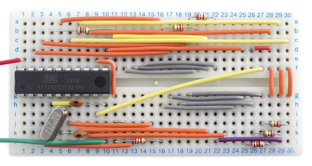
Interconnections under the dot matrix displays.
The circuit fits neatly on a small solderless breadboard I bought from Bright Components on eBay [2].
Uploading the program
I developed the program using the Arduino IDE and used the Tiny AVR Programmer [3] to upload it to the ATtiny2313 on the breadboard; see ATtiny-Based Beginner's Kit. Plug the Tiny AVR Programmer into the computer's USB port, and then connect it to the ATtiny2313 using six jumper wires:
Connecting the Tiny AVR Programmer to the ATtiny2313.
Compile the program using Spence Konde's ATTiny Core [4]. Choose the ATtiny2313/4313 option under the ATTinyCore heading on the Board menu. Then check that the subsequent options are set as follows (ignore any other options):
Chip: "ATtiny2313"
Clock: "8 MHz (external)"
B.O.D: "B.O.D. Disabled"
Choose Burn Bootloader to set the fuses appropriately. Then choose Upload to upload the program to the ATtiny2313.
Here's the whole program for the Dot Matrix Clock: Dot Matrix Clock Program.
Customisation
The nice thing about using dot matrix displays is that, subject to the limitations of the wiring, you can customise the display digits to suit your preferences. For example, here are some alternative character definitions for rounded digits:
char CharMap[11][3] = {
{ 0x3E, 0x41, 0x3E }, // 0
{ 0x00, 0x20, 0x7F }, // 1
{ 0x27, 0x49, 0x31 }, // 2
{ 0x2A, 0x49, 0x36 }, // 3
{ 0x18, 0x28, 0x7F }, // 4
{ 0x7A, 0x49, 0x4E }, // 5
{ 0x3E, 0x49, 0x26 }, // 6
{ 0x47, 0x48, 0x70 }, // 7
{ 0x36, 0x49, 0x36 }, // 8
{ 0x32, 0x49, 0x3E }, // 9
{ 0x00, 0x00, 0x00 }, // space
};
Or, design your own font!
Update
5th October 2020: I now recommend using Spence Konde's ATTinyCore to compile and upload the program, and I've rewritten the description accordingly. I've also updated the program to work with this core.
- ^ Miniature Ultra-Bright 8x8 White LED Matrix on Adafruit.
- ^ Solderless Prototype Breadboard (360 Points) from Bright Components on eBay.
- ^ Tiny AVR Programmer on SparkFun.
- ^ ATTinyCore on GitHub.
blog comments powered by Disqus