ATtiny85 Bargraph Voltmeter
20th December 2015
This article describes a simple bargraph display driven by an ATtiny85. It measures the voltage on an analogue input, and displays it by lighting up from 0 to 10 bars on the display. It could be used as a battery level indicator, or as the display for a sensor such as a thermometer:
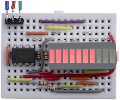
ATtiny85 Bargraph Voltmeter displays an analogue voltage as a bar.
For the display I used a low-cost red 10-LED bargraph display, available from Sparkfun [1], or HobbyTronics in the UK [2]. Alternatively you could use discrete LEDs.
Charlieplexing
The circuit takes advantage of the fact that these bargraph displays give you separate access to the anodes and cathodes of each LED in the package, so we can use charlieplexing to drive the ten LEDs from just four I/O lines. If the package joined all the anodes or cathodes to a common terminal we would need 10 I/O lines to drive them, more than is available on the ATtiny85.
The multiplexing works by taking one I/O line low at a time, to select one row of LEDs by taking their cathodes low. The appropriate LEDs in that row are then illuminated by taking their anodes high. Any unused I/O lines are left as inputs, so they are high-impedance.
The following diagram shows how the anodes and cathodes of the ten LEDs, numbered 0 to 9, are connected to the four I/O lines, PB0, PB1, PB3, and PB4:
For example, to light up bars 3 and 4 on the bargraph take PB1 low, and PB3 and PB4 high.
The grey squares show positions where you can't connect an LED, because an I/O line can't be both high and low at the same time. The two blank cells could be used to connect two more LEDs, to create a 12-bar bargraph.
The program would have been slightly simpler if I'd used PB0, PB1, PB2, and PB3 to drive the display, and ADC2 (PB4) for the ADC input, but I decided to use ADC1 (PB2) for reasons that will become clear in a subsequent article.
Multiplexing the display
The display is generated under interrupt, using the contents of the variable Display. For example, to display a bar of seven segments, as in the above photograph, execute:
Display = 0x007F;
The display is multiplexed using Timer/Counter0, leaving Timer/Counter1 free for use by Millis() and Delay(). It is configured in setup() to generate an interrupt at 625Hz:
  TCCR0A = 2<<WGM00;                     // CTC mode
  TCCR0B = 3<<CS00;                      // /64 prescaler
  OCR0A = 24;                            // 625 Hz interrupt
  TIMSK = TIMSK | 1<<OCIE0A;             // Enable interrupt
Each set of LEDs is on for a fifth of this time, or 125Hz, which is safely above the frequency at which flicker would be noticable.
The compare match interrupt service routine then lights up the appropriate set of LEDs:
ISR(TIMER0_COMPA_vect) {
  int Data;
  Row = (Row + 1) % 5;
  DDRB = 0;  // Make all pins inputs
  if (Row == 0) Data = (Display & 0xC0)>>3 | (Display & 0x20)>>4;
  else if (Row == 1) Data = Display & 0x18;
  else if (Row == 3) Data = Display>>8 & 0x03;
  else if (Row == 4) Data = (Display & 0x03) | (Display & 0x04)<<1;
  else { Display = Bar(ReadADC()/100); return; }  // When Row=2 read ADC
  PORTB = (PORTB | Data) & ~(1<<Row);    // Take row low
  DDRB = DDRB | Data | 1<<Row;           // Make row an output
}
This reads the data in Display and lights the LEDs for the current row, as specified by the value of Row.
Analogue to digital conversion
The ADC in the ATtiny85 is driven by a clock which is divided down from the system clock; the datasheet recommends an ADC clock of between 50kHz and 200kHz, so I chose a prescaler of 16 which gives a frequency of 62.5kHz. A conversion takes 13 cycles, so we can do about 4800 conversions per second.
The ADC is configured and enabled in setup():
  ADMUX = 2<<REFS0 | 1<<REFS2 | 1<<MUX0; // Internal 2.56V ref, ADC1 (PB2)
  ADCSRA = 1<<ADEN | 4<<ADPS0;           // Enable, 62.5kHz ADC clock
To avoid noise on the ADC the datasheet recommends that "if any port pin is used as a digital output, it mustn’t switch while a conversion is in progress". The solution I chose was to integrate the conversion into the display loop; when Row is 2 the display loop blanks the display and performs an ADC conversion rather than lighting the LEDs.
The ADC conversion is performed by ReadADC():
unsigned int ReadADC() {
  unsigned char low,high;
  ADCSRA = ADCSRA | 1<<ADSC;             // Start
  do ; while (ADCSRA & 1<<ADSC);         // Wait while conversion in progress
  low = ADCL;
  high = ADCH;
  return (high<<8 | low);
}
The following line in the interrupt service routine displays the scaled output from the ADC, converted to a bar of between 0 and 10 LEDs:
Display = Bar(ReadADC()/100);
Each LED corresponds to a voltage of 0.25V, so 7 bars corresponds to 1.75V. You can increase the sensitivity to up to 2.5mV per LED by adjusting the scale factor.
Alternatively, if you prefer a line display, with only one bar lit at a time, replace this by:
Display = Line(Read(ADC)/100);
When I was debugging the analogue input I displayed the output from the ADC as a binary number (reversed) on the display using:
Display = ReadADC();
Bar
Bar(n) takes a number from 0 to 10 and returns a number consisting of a bar of the corresponding number of '1' bits:
int Bar (int n) { return ((signed int) 0x8000 >> (15-n))^0xFFFF; }
Line
Line(n) takes a number from 0 to 10; 0 returns 0, and 1 to 10 return a number with the corresponding single bit set to '1':
int Line (int n) { return (1 << n) >> 1; }
Circuit
The circuit neatly fits on a mini breadboard; I use the ones from SparkFun [3] or HobbyTronics in the UK [4]. Here's the circuit, which roughly follows the way it was laid out on the breadboard:
Circuit of the ATtiny85 Bargraph Voltmeter.
The circuit is powered from between 3V and 5V.
Compiling the program
I compiled the program using the Arduino-Tiny core extension to the Arduino IDE [5]. Select the ATtiny85 @ 1 MHz (internal oscillator; BOD disabled) option on the Boards menu. This is the default fuse setting on new ATtiny85s; otherwise choose Burn Bootloader to set the fuses appropriately. Then upload the program to the ATtiny85 using the Tiny AVR Programmer Board; see ATtiny-Based Beginner's Kit.
Here's the whole ATtiny85 Bargraph Voltmeter program: Bargraph Voltmeter Program.
- ^ 10 Segment LED Bar Graph - Red on SparkFun.
- ^ 10 Bar Red DIL LED Display on HobbyTronics.
- ^ Breadboard - Mini Modular on SparkFun.
- ^ Mini Breadboard from HobbyTronics.
- ^ Arduino-Tiny core on Google Code.
blog comments powered by Disqus