Minimal ATSAMD21 Computer 2
19th March 2019
Last week I described how to build an ATSAMD21-based computer on a prototyping board using a 32-pin ATSAMD21E with the minimum number of components, and program it from the Arduino IDE.
This article shows how to follow the same procedure with the larger 48-pin ATSAMD21G:
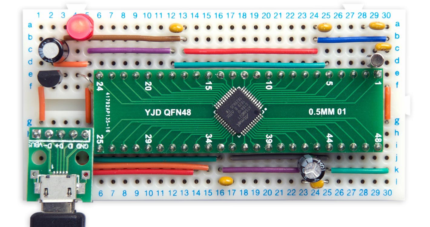
Minimal computer on a breadboard, based on an ATSAMD21G.
As before, you first need to upload a bootloader to the bare ATSAMD21 chip, using the Arduino IDE and an Arduino Zero as a programmer. You can then program the minimal ATSAMD21 computer from the Arduino IDE via the USB port, like any other Arduino board.
Like the ATSAMD21E, the ATSAMD21G is an ARM Cortex M0+ processor with up to 256KB flash memory, 32KB RAM, and a 48MHz clock. However, this has 48 pins rather than the 32 pins of the smaller chip, which gives you 38 I/O pins rather than 26 in the smaller chip, and 14 rather than 10 ADC channels. I recommend getting the variant with the maximum 256KB flash memory and 32KB RAM, the ATSAMD21G18A.
The circuit
Here's the circuit of the 48-pin ATSAMD21G version of the minimal ATSAMD21 computer:
Circuit of the minimal computer based on an ATSAMD21G.
I mounted the ATSAMD21G on a 48-pin breakout board from AliExpress [1]. As in the ATSAMD21E version it was easier to connect the two crystal capacitors to Vcc on the prototyping board; it makes no difference. The 330Ω resistor is tucked under the breakout board as there's nowhere else to fit it. The other components are the same as the ATSAMD21E version.
Testing the circuit
As before, when you first connect power to the circuit I recommend monitoring the current consumption, as this will quickly give you an indication of whether there are any shorts or incorrect connections.
The expected current consumption at 3.3V is about 12mA. If you're getting much more than this, quickly disconnect the supply and check your wiring. If you're only getting around 0.3mA your crystal may not be oscillating; check the connections to the crystal and the crystal capacitors.
Uploading a bootloader
As described in the earlier article, there are two alternative ways to upload a bootloader using just the Arduino IDE and another Arduino ATSAMD21 board:
- Uploading a bootloader using EDBG on an Arduino Zero board
- Uploading a bootloader from an SD card using DAP
Arduino pin assignments
Using the Arduino/Genuino Zero (Native USB Port) board setting the ATSAMD21G pins will map to the Arduino core functions as shown in the following diagram:
Pins marked '~' can be used with analogWrite(). The pins shown in yellow are the additional pins not present in the 32-pin ATSAMD21E,
Upload Blink
To test the board you can upload the Arduino Blink example. Here for a bit of variety is a version that toggles the pin PA17 directly, without using digitalWrite():
void setup() {
  REG_PORT_DIR0 |= PORT_PA17; // Make PA17 an output
}

void loop() {
  REG_PORT_OUT0 ^= PORT_PA17; // Toggle PA17
  delay(1000);
}
Upload uLisp
As in the earlier article you might like to try running the ARM version of my Lisp interpreter, uLisp, on the minimal ATSAMD21 board. Download it here: Download uLisp
In the Arduino/Genuino Zero board definition the native USB port is called SerialUSB, so before uploading uLisp add the following line at the beginning of the file (or the Serial Monitor won't work):
#define Serial SerialUSB
Intelligent blink
Here's a variant of the classic Aduino Blink program that blinks out the series of prime numbers, starting with 2, 3, 5, 7, 11, etc, up to the largest integer that uLisp can represent, 32767. You could also use this to demonstrate the existence of intelligent life to visiting aliens.
First, the routine pri returns t if its argument is prime, and nil if it’s composite:
(defun pri (n)
  (let ((d 2))
    (loop
     (when (> (* d d) n) (return t))
     (when (zerop (mod n d)) (return nil))
     (incf d))))
Here's the Blink program:
(defun bli ()
  (pinmode 13 t)
  (dotimes (x 32767)
     (when (and (> x 1) (pri x))
         (dotimes (f (* x 2))
           (digitalwrite 13 (evenp f))
           (delay 250))
         (delay 1500))))
Copy and paste each routine into the Serial Monitor to enter it into uLisp, and then run it with:
(bli)
To exit from the program enter ~ and press Return.
- ^ QFN adapter plate 48p on AliExpress.
blog comments powered by Disqus