Four-Channel Thermometer
29th August 2017
This article describes a four-channel thermometer that monitors the temperature at four temperature sensors, and gives a continuous readout on a small 128x32 OLED display:
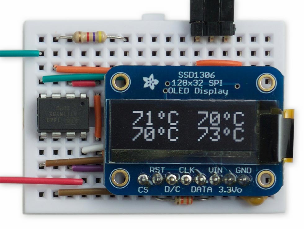
Four-Channel Thermometer uses an ATtiny85 to read four DS18B20 1-Wire sensors.
It could be used in any application where you want to monitor multiple temperatures, such as in controlling a greenhouse, checking the output transistors in a power amplifier, monitoring key points in an overclocked gaming PC, monitoring the chips on a Raspberry Pi, or checking the temperature in different rooms in a home.
Here's an example of using the Four-Channel Thermometer to monitor the temperature of the power transistors in a Class A power amplifier:
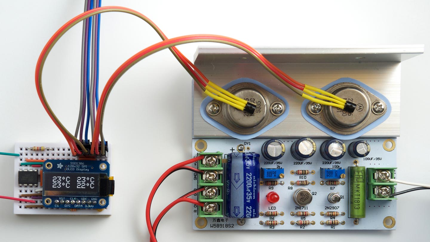
Using the Four-Channel Thermometer to monitor the power transistors in a Class A power amplifier.
Introduction
The Four-Channel Thermometer uses an ATtiny85 to read the data from four DS18B20 or MAX31820 temperature sensors, using the 1-Wire protocol, and display the temperatures on a small OLED display.
For the display I chose a 128x32 OLED display, a small display about 2.5cm (1") wide with a very clear, bright monochrome display, and an SPI interface, available from Adafruit [1]. A similar display is also available from Aliexpress [2].
For the sensors I used DS12B20 [3] temperature sensors in a TO-92 transistor package, which have a supply range of 3.0V to 5.5V. The MAX31820 [4] is equivalent and cheaper, but has a maximum supply voltage of 3.7V. Alternatively you can find a pack of 10 DS18B20s on Banggood [5]. The DS18B20 temperature sensors are also available encapsulated into a waterproof cable [6].
You can connect to the temperature sensors using twisted-pair cables of several metres; with long cables a linear topology is recommended rather than a star configuration [7].
The program uses the simple 1-Wire routines from my earlier project, Simple 1-Wire Interface.
Here's the full circuit:
The circuit of the Four-Channel Thermometer, based on an ATtiny85.
The 33kΩ resistor and 0.1µF capacitor ensure that the display is reset correctly when power is first applied.
Using the Four-Channel Thermometer
To use the Four-Channel Thermometer you first need to set it up as follows:
- Connect one of the DS18B20/MAX31820 temperature sensors you are going to use, and apply power.
The sensor's serial number will be read and stored in EEPROM on the ATtiny85, and the display should show the temperature in the first display position.
- Disconnect power, remove the first temperature sensor, connect the second temperature sensor, and apply power again.
The second sensor's serial number will be read and stored in EEPROM. The display should show an 'X' in the first display position, since that position is already allocated, and the temperature in the second display position.
- Repeat for the remaining two temperature sensors.
- Finally, disconnect power, connect all four temperature sensors to the 1-Wire bus, and reconnect power.
The display will show all four temperatures, dynamically updated.
Note that if you try running the program without any sensors connected the display will show "?". If you connect two or more sensors at once, without first doing the "training" procedure, the display will remain blank.
How it works
All 1-Wire devices are programmed with a unique 48-bit serial number in ROM, to allow you to identify multiple devices connected to the same 1-Wire bus.
To read the temperature from a specific DS18B20/MAX31820 sensor you need to send a Match ROM command, followed by the serial number of the sensor you want to access.
To find the serial numbers of all the devices on the 1-Wire bus you can use a special routine called Search ROM, which tests the 48 bits a bit at a time for conflicts, and then builds a tree of the device serial numbers. This is a complex procedure; if you want to do it this way use one of the 1-Wire libraries. Fortunately, there's a much simpler way of finding the serial numbers: you can connect the devices to the 1-Wire bus one at a time, and use the Read ROM command to read each serial number directly. This is the method I use in this application.
The Four-Channel Thermometer uses the EEPROM on the ATtiny85 to store the signatures of the four temperature sensors. To "train" the Four-Channel Thermometer you connect one of the four temperature sensors you are going to use, and apply power. In setup() the program tries the Read ROM command, and if the data read back has a valid CRC it knows that it has read a valid serial number, and this is stored in EEPROM:
  // Check if there's something on the bus
  cli();
  if (OneWireReset() != 0) { PlotChar('?',1,10); for(;;); }
  int slot;
  // Find the first free EEPROM slot
  for (slot=0; slot<4; slot++) {
    if (EepromLoad(slot) != 0) break;
  }
  if (slot < 4) {
    // Try reading the ROM
    OneWireWrite(ReadROM);
    OneWireReadBytes(8);
    sei();
    if (OneWireCRC(8) == 0) {
      // Check we haven't already got it
      int j;
      for (j=0; j<slot; j++) {
        if (EepromCompare(j)) break;
      }
      // Save it into the slot
      if (j == slot) EepromSave(slot);
    }
  }
Having trained up to four sensors, you can then connect them all to the circuit. This time the Read ROM command fails, because of a bus collision, so the training stage of the program is ignored.
Note that if for some reason you want to erase the serial numbers stored in EEPROM, for example to use different sensors, remove all the sensors, uncomment the EepromClear() call at the start of setup(), and then run the program once.
Displaying the temperatures
The main routine, in loop(), reads each of the signatures in turn from EEPROM, accesses the appropriate sensor using the Match ROM command, reads back the temperature, and calls PlotTemperature() to display it in the appropriate position on the display:
void loop () {
  for (int i=0; i<4; i++) {
    int line = (i / 2)*2;
    int col = (i % 2)*11;
    // Display temperatures of all devices on bus
    cli();                            // No interrupts
    if (OneWireReset() != 0) {
      sei();
      PlotChar('?', line, col);
    } else if (EepromLoad(i) == 0) {
      OneWireWrite(MatchROM);
      OneWireWriteBytes(8);
      OneWireWrite(ConvertT);
      while (OneWireRead() != 0xFF);
      OneWireReset();
      OneWireWrite(MatchROM);
      OneWireWriteBytes(8);
      OneWireWrite(ReadScratchpad);
      OneWireReadBytes(9);
      sei();                          // Interrupts
      if (OneWireCRC(9) == 0) {
        int temp = DataBytes[1]<<8 | DataBytes[0];
        PlotTemperature(temp>>4, line, col);
      } else PlotChar('X', line, col);
    }
  }
}
If there's a CRC error in reading one of the temperatures the program displays "X" in that position. This usually means you've disconnected that sensor.
The cli() and sei() calls disable interrupts around the 1-Wire routines; they are optional, but without them a temperature reading occasionally gives a CRC error due to the Arduino millis() interrupts.
The temperatures are written to the display by the routine PlotTemperature(), which calls PlotChar() to plot the individual characters of the temperature in a field width of five characters, from -99°C to 999°C. This covers the range supported by the DS18B20, -55°C to 125°C:
void PlotTemperature (int temp, int line, int column) {
  boolean dig = false;
  unsigned int j = 100;
  if (temp < 0) {
    PlotChar('-', line, column);
    temp = - temp;
    column = column + Scale;
    j = 10;
  }
  for (int d=j; d>0; d=d/10) {
    char c = DigitChar(temp, d);
    if (c == '0' && !dig) c = ' '; else dig = true;
    PlotChar(c, line, column);
    column = column + Scale;
  }
  PlotChar('`', line, column); column = column + Scale;
  PlotChar('C', line, column);
}
Plotting characters
To avoid the need for a memory buffer, which would require 512 bytes or RAM, beyond what's available on the ATtiny85, the characters are drawn directly from the character definitions to the display.
For flexibility the PlotChar() routine provides the option of displaying either normal-sized characters, on a 6x8 pixel character cell, or double-sized characters, which occupy 12x16 pixels. You can fit four temperatures in °C on the display using double-sized characters, which makes the display more readable. If you want to display more channels, or tenths of a degree precision, you can use the normal-size characters, or have a mixture of both. The character size is controlled by the global variable Scale:
void PlotChar(char c, int line, int column) {
  PINB = 1<<cs; // cs low
  // Set column address range
  Command(0x21); Command(column*6); Command(column*6 + Scale*6 - 1);
  // Set page address range
  Command(0x22); Command(line); Command(line + Scale - 1);
  for (uint8_t col = 0 ; col < 6; col++) {
    int bits = pgm_read_byte(&CharMap[c-32][col]);
    if (Scale == 1) Data(bits);
    else {
      bits = Stretch(bits);
      for (int i=2; i--;) { Data(bits); Data(bits>>8); }
    }
  }
  PINB = 1<<cs; // cs high
}
The parameters line and column specify the position on the screen that the character is plotted, in normal-sized characters; so line can be between 0 and 5, and column can be between 0 and 20, with (0, 0) corresponding to the top left character position.
The graphics display is based on my earlier project Tiny Terminal, modified for a 128x32 display, and the technique of displaying double-sized characters is from my project Big Text for Little Display.
Compiling the program
Compile the program using Spence Konde's ATTiny Core [8]. Choose the ATtiny25/45/85 (No bootloader) option under the ATTinyCore heading on the Board menu. Then check that the subsequent options are set as follows (ignore any other options):
Chip: "ATtiny85"
Clock: "8 MHz (internal)"
Choose Burn Bootloader to set the fuses appropriately for this frequency option. Then upload the program using ISP (in-system programming); I used Sparkfun's Tiny AVR Programmer Board; see ATtiny-Based Beginner's Kit.
Here's the whole Four-Channel Thermometer program: Four-Channel Thermometer Program.
Further suggestions
The nice thing about 1-Wire is that it's easy to add further devices, by daisy-chaining them to the 1-Wire bus. You can of course add further DS18B20 or MAX31820 temperature sensors, to cater for more measurements. You could add a time display using the DS2417, which is a 1-Wire crystal-controlled real-time clock; for an example see Tiny Time 2 Watch. You could add non-volatile memory for data logging using one of the 1-Wire non-volatile memory chips, such as the DS28EC20, which gives 20 Kbits of non-volatile memory. You could also add a 1-Wire switch, such as the DS2413 or DS2408, to control external devices, although it would probably make more sense to use an ATtiny chip with more outputs, such as the ATtiny84, instead.
Updates
9th May 2018: Corrected the declaration of the character map from uint32_t to uint8_t.
5th December 2020: I have rewritten the section "Using the Four-Channel Thermometer" to make it a bit clearer, and have incorporated the character smoothing described in Smooth Big Text.
- ^ Monochrome 128x32 SPI OLED graphic display on Adafruit.
- ^ 0.91 Inch SPI 128x32 White OLED LCD Display on Aliexpress.
- ^ One Wire Digital Temperature Sensor - DS18B20 on Sparkfun
- ^ One-Wire Ambient Temperature Sensor - MAX31820 on Sparkfun
- ^ 10 Pcs DS18B20 Temperature Sensor on Banggood.
- ^ Temperature Sensor - Waterproof (DS18B20) on Sparkfun.
- ^ Guidelines for Reliable Long Line 1-Wire Networks on Maximintegrated.com.
- ^ ATTinyCore on GitHub.
blog comments powered by Disqus