Waveform Generation using an ATtiny85
5th October 2014
This article describes how to generate different waveform shapes using Direct Digital Synthesis or DDS on an ATtiny85. This program forms the basis for a simple synthesiser that I plan to describe in a later article.
Introduction
The simplest way to play tunes on an Arduino, or other AVR chip, is to use one of the timer/counters to divide the clock frequency by a divisor corresponding to the note you want to play. The smaller the divisor, the higher the frequency. This is how the Arduino's Tone() function works, using Timer/Counter2. See my post Simple Tones for ATtiny for one approach to getting tones on the ATtiny85.
An alternative approach is to calculate the final mixed waveform digitally, and send it to the speaker using a digital-to-analogue converter. This is called Direct Digital Synthesis or DDS. You need a table of a pre-computed waveform, such as a sine wave. To generate a particular frequency you step through the table selecting every nth sample. The smaller the number used to step, the longer it takes to get around one cycle of values, and so the lower the frequency.
Synthesisers using DDS with tables of waveforms are called wavetable synths, and there have been some excellent articles describing wavetable synths using Atmel AVR processors [1] [2] [3]. The advantage of the DDS approach are:
- You don't need to mix together the outputs from each timer/counter; it's done automatically when you sum the accumulators.
- You can have an arbitrary number of voices, limited only by the processor speed.
- You can create waveforms other than a simple square wave.
- And finally, you can provide an envelope to each note, by multiplying the note by amplitude values.
The disadvantage of wavetable synths is that they need additional memory to store the wavetables. This article describes a simpler approach involving dynamically generating the waveforms to avoid the need for wavetables [4].
Generating waveforms
The ATtiny85 is ideal for DDS as it has a special 64MHz clock option which you can use to drive Timer/Counter1 for fast digital-to-analogue conversion. To test the DDS with different waveform shapes I created the following program, which generates a single continuous waveform:
/*
 Generating a tone using DDS
*/

unsigned int Acc;
unsigned int Note = 857; // Middle C

void setup() {
  // Enable 64 MHz PLL and use as source for Timer1
  PLLCSR = 1<<PCKE | 1<<PLLE;

  // Set up Timer/Counter1 for PWM output
  TIMSK = 0;                     // Timer interrupts OFF
  TCCR1 = 1<<CS10;               // 1:1 prescale
  GTCCR = 1<<PWM1B | 2<<COM1B0;  // PWM B, clear on match

  pinMode(4, OUTPUT);            // Enable PWM output pin

  // Set up Timer/Counter0 for 20kHz interrupt to output samples.
  TCCR0A = 3<<WGM00;             // Fast PWM
  TCCR0B = 1<<WGM02 | 2<<CS00;   // 1/8 prescale
  TIMSK = 1<<OCIE0A;             // Enable compare match, disable overflow
  OCR0A = 49;                    // Divide by 400
}

void loop() { }

ISR(TIMER0_COMPA_vect) {
  Acc = Acc + Note;
  OCR1B = (Acc >> 8) & 0x80;
}
The first section turns on the 64MHz Phase-Locked Loop (PLL), and specifies this as the clock source for Timer/Counter1.
Timer/Counter1 is then set up in PWM mode, to make it act as an digital-to-analogue converter, using the value in OCR1B to vary the duty cycle. The frequency of the square wave is specified by OCR1C; we leave it at its default value, 255, which divides the clock by 256, giving a 250kHz square wave.
Timer/Counter0 is used to generate an interrupt to output the samples. The rate of this interrupt is the 8MHz system clock divided by a prescaler of 8, and a value in OCR0A of 49+1, giving 20kHz. The interrupt calls an Interrupt Service Routine ISR(TIMER0_COMPA_vect) which calculates and outputs the samples.
As an example, here's the calculation showing what note you get for the specified value of Note, 857. The Interrupt Service Routine is called once every 20kHz, and each time Note is added into the 16-bit phase accumulator, Acc. The top bit of Acc will therefore change with a frequency of 20000/(65536/857) or 261.5 Hz, middle C.
Square wave
The simplest waveform to generate is the square wave. This has a rich sound because it contains all the odd harmonics, and sounds a bit like a wind instrument. Here's an oscilloscope trace of the waveform [5]:
The ISR in the above program generates a square wave using DDS by taking the top bit of the accumulator:
ISR(TIMER0_COMPA_vect) {
  Acc = Acc + Note;
  OCR1B = (Acc >> 8) & 0x80;
}
Sawtooth wave
The sawtooth wave has an amplitude that counts up from 0 to 255 each cycle, so named because it looks like the teeth of a saw. It contains all the harmonics, and sounds quite harsh, like a violin note.
To generate the sawtooth wave replace the ISR routine with this code, which takes the top eight bits of the accumulator:
ISR(TIMER0_COMPA_vect) {
  Acc = Acc + Note;
  OCR1B = Acc >> 8;
}
Triangle wave
The triangle wave counts up from 0 to 127, and then back down to 0 again. It is close to a pure sinewave in shape, but with the addition of the odd harmonics at lower levels than the square wave. It sounds close to a pure tone, like a bell.
To generate the triangle wave replace the ISR routine with this code, which takes the top eight bits of the accumulator, and inverts them when the top bit is set:
ISR(TIMER0_COMPA_vect) {
  signed char Temp, Mask;
  Acc = Acc + Note;
  Temp = Acc >> 8;
  Mask = Temp >> 7;
  OCR1B = Temp ^ Mask;
}
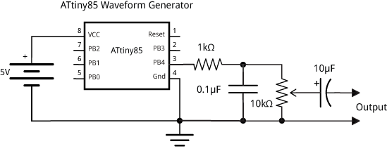
Circuit
The circuit includes a simple low-pass filter to filter out the sampling frequency; the output is then suitable for earphones or an audio amplifier:
For a simple ATtiny85-based four-voice synthesiser using these techniques see Tiny Synth.
For a function generator based on these techniques see Tiny Function Generator.
- ^ Arduino DDS Sinewave Generator on LabIII
- ^ The Synth by GeekPhysical on GitHub (demos)
- ^ Wavetable Melody Generator on ELM - ChaN.
- ^ Thanks to Chris Jordan for suggesting the techniques developed in this article.
- ^ The oscilloscope traces were captured using a JYE Tech DSO 062 Digital Storage Oscilloscope available from Watterott.
blog comments powered by Disqus