Getting Extra Pins on ATtiny
4th June 2014
Part of the fun of designing with the ATtiny85 and ATtiny84 ranges is trying to shoehorn your project into the tiny package. I'm sure I'm not the first person who has run out of I/O pins while trying to use one for a project. Here are some tips I've discovered for making better use of the existing pins, or finding an extra pin.
Sharing inputs
How many inputs do you need to use to sense n pushbuttons?
The simplest method is to connect each pushbutton to a separate input. This requires n inputs.
For more than four pushbuttons it is better to arrange the pushbuttons into a x by y matrix, and multiplex them. This requires x+y inputs, so for 16 pushbuttons you need 8 inputs, or for n pushbuttons you need about root n inputs.
A less obvious trick is to connect several pushbuttons to a single analogue input using a resistor ladder to give each button a different voltage. Here's an example with five buttons:
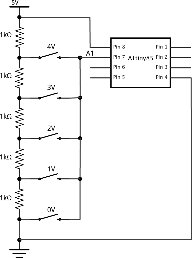
Connecting five pushbuttons to a single input.
The 1kΩ resistors form a voltage divider, giving outputs of 0V, 1V, 2V, 3V, and 4V. With no button pressed the analogue input A0 is floating, so the internal pullup resistor should be enabled. Pressing a button sets A0 to the corresponding voltage.
To read which pushbutton is pressed we just need to do:
button = (analogRead(A0)*5+512)/1024;
which returns a number between 0 and 5.
The advantage of the above design is that it uses five identical resistors, so it's easy to construct. The disadvantage is that it draws current even when no button is pressed; in this case 1mA. Here's an alternative design that solves this problem:
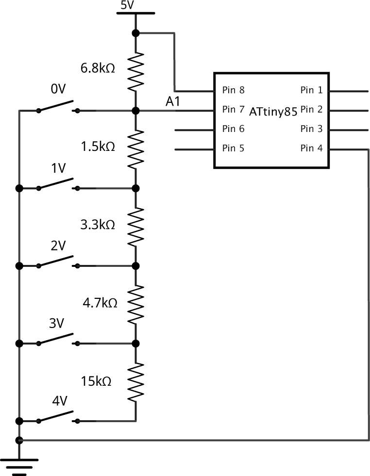
Connecting five pushbuttons to a single input.
Again, this gives voltages of 0V, 1V, 2V, 3V, and 4V, or 5V with no button pressed, but has the advantage that it draws no current when no button is pressed, and no pullup is needed. The resistors need to be in the ratios 12, 3, 5, 10, 30, but can be any suitably close values. I ran a program to find the best values from the E6 series; the values shown above produce voltages within 10% of the required values. Again, to read which pushbutton is pressed just do:
button = (analogRead(A0)*5+512)/1024;
Using a pin as both an input and an output
Suppose you've got one pin available and you need to display status on an LED, and sense a pushbutton. One option is to use the same pin as both an input and an output:
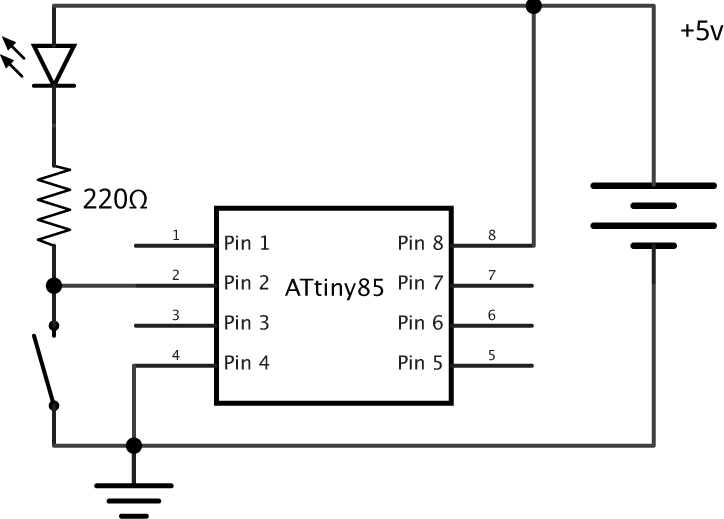
Using a pin as both an input and an output.
Set the output low when you want to turn on the LED. Program it as an input when you want to turn off the LED, or read the pushbutton. You shouldn't set the output high since the pushbutton could then short the output to ground; to protect against this connect a second 220Ω resistor in series with the switch.
The only limitation is that the LED lights up while the pushbutton is pressed, but if the LED is showing the status of an option selected by the pushbutton that may actually be appropriate.
Here's a simple program that demonstrates this circuit; the LED is normally off, but pressing the pushbutton latches it on for one second:
int led = 3;

void setup() {
  digitalWrite(led, LOW);
  pinMode(led, INPUT);
}

void loop() {
  // Read input
  if (digitalRead(led) == LOW) {
    // Turn LED on
    pinMode(led, OUTPUT);
    delay(1000);
    // Turn LED off
    pinMode(led, INPUT);
  }
}
Using the reset pin on the ATtiny85
As is well known you can reprogram the internal fuses to reclaim the reset pin as an extra I/O pin. What is less well-known is that you can actually use the reset pin in a limited way on the ATtiny85 without having to reprogram the fuses, provided you avoid taking it below about 2.5V which will reset the chip.
Here's the program I used to test this on an ATtiny85 using the 1MHz internal clock:
/* Using the Reset pin as ADC0 */

const int Speaker = 3;

// Beep out a 10-bit binary number, LSB first
void debug (unsigned int thing) {
  for (unsigned int b=1; b!=1024; b = b<<1) {
    for (unsigned int i=0; i<1250; i++) {
      if (thing & b) digitalWrite(Speaker, (i & 16));
      else digitalWrite(Speaker, (i & 32));
    }
    for (unsigned int i=0; i<1250; i++) digitalWrite(Speaker, 0);
  }
}

void setup() {
  pinMode(Speaker, OUTPUT);
}

void loop() {
   debug(analogRead(0));
   delay(2000);
}
To reveal the ADC reading I've connected a piezo speaker between PB3 and ground, and I'm using a simple debug routine which beeps out the ten-bit ADC value as a series of low and high beeps, LSB first, with a low beep representing a 0 and a high beep representing a 1.
I tested it by connecting a potentiometer across the supply, with the wiper connected to the reset pin. Here are the results:
- 5v - reading 0b11111111 or 1023
- 2.2V - reading 0b0111000011 or 451
- Below 2.2V - ATtiny85 reset
This corresponds to the datasheet, and gives us a range of 2.8V over which we can use the reset pin for analogue measurements.
One simple application is to sense a pushbutton that switches ADC0 between 3v and 5v:
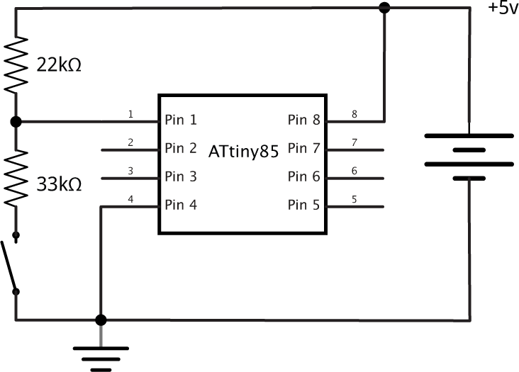
Using the reset pin on the ATtiny85.
Reprogramming the fuses to use the reset pin as an I/O pin
If all else fails you can reprogram the fuses to use the reset pin as another I/O pin. This will enable you to use it as a digital or analogue input, or as an output to flash an LED:
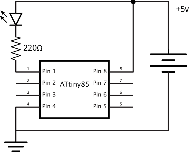
Reprogramming the fuses to use the ATtiny85 reset pin as an I/O pin.
The problem is that once you have done that you will no longer be able to upload a program using an ISP programmer without first resetting the fuses using a high voltage programmer.
Here's the full procedure. First upload the program that will use the Reset pin. I'm using a simple Blink program to blink an LED, using the Reset pin as an output:
/* Blink Reset pin */

int led = 5; // Reset pin

void setup() {
  DDRB = 1<<led;
}

void loop() {
  PINB = 1<<led;
  delay(1000);
}
To program the ATtiny85 I used Sparkfun's Tiny AVR Programmer [1]. To use this with the Arduino IDE install the ATtiny microcontroller support for the Arduino IDE.
The simplest way is to use a high-voltage programmer, which lets you set the fuses to anything you want. You can use an Arduino Uno as a high-voltage programmer [2]. Alternatively Proto-Pic in the UK used to sell a high-voltage programmer shield which used a 12V external power supply. Unfortunately this is no longer available.
// Desired fuse configuration
#define  HFUSE  0x5F
#define  LFUSE  0x62
and run the program to set the RSTDISBL fuse.
Now if you put the ATtiny85 back in the circuit the LED connected to pin 1, the reset pin, should flash as required. Note that the reset pin doesn't have such a high drive capability as the other pins, so the LED will be dimmer than an LED on pins 0 to 4.
Resetting the fuses to their defaults
If you've set the RSTDISBL fuse ISP programming will no longer work; next time you try to upload a program using the Tiny AVR Programmer you'll get the error:
avrdude: initialization failed, rc=-1
You will need to reset the fuses to their default values using the High-Voltage Programmer again before proceeding.
- ^ Tiny AVR Programmer Hookup Guide on SparkFun.
- ^ ATtiny Fuse Reset on Wayne's Tinkering Page.
blog comments powered by Disqus