RA4M1 Nano Board
16th January 2024
This is a microcontroller board based on the Renesas RA4M1 ARM processor, compatible with the new Arduino Uno R4 Minima [1] but in the same form factor as the Arduino Nano:
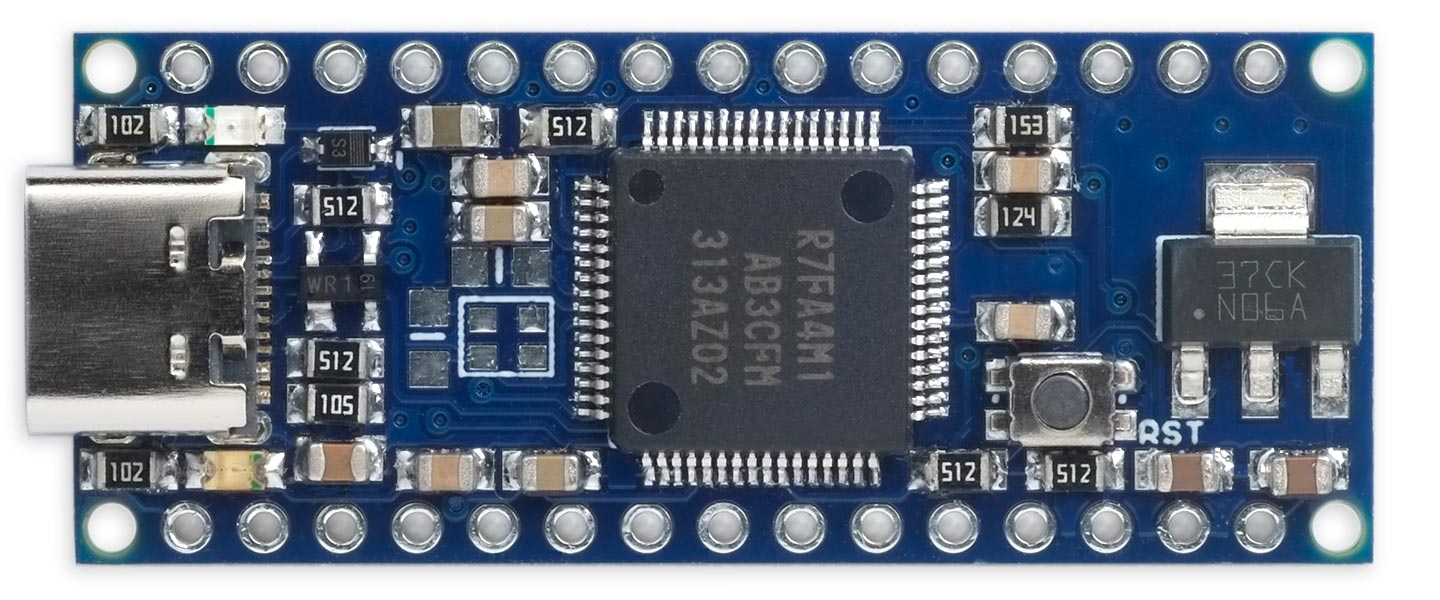
The RA4M1 Nano, an Arduino Nano-sized board based on the Renesas RA4M1 ARM processor.
Like the Arduino Uno R4 Minima it runs at 48MHz, has 32KB of RAM and 256KB of flash, and its I/O pins use 5V logic. In addition to all the standard peripherals it also includes a 12-bit DAC and an op-amp.
Introduction
I was intrigued when Arduino announced the Uno R4 Minima board earlier this year. It is a board in the same format as the original ATmega328P-based Arduino Uno, but instead based on the RA4M1 ARM processor from the Japanese semiconductor manufacturer Renesas. An unusual feature of this processor is that it is capable of running from a 5V supply, making the Arduino Uno R4 Minima compatible with peripherals designed for the original Arduino Uno without needing logic-level translation.
I signed up for the Arduino Uno R4 Early Access Program, as I was interested in testing the board with my Lisp interpreter, uLisp, and giving feedback. The ARM version of uLisp now supports this RA4M1 Nano board, the Arduino Uno R4 Minima, and its companion the Arduino Uno R4 WiFi: Arduino Uno R4 Boards.
After experimenting with the Arduino Uno R4 Minima I thought it would be fun to design a smaller RA4M1 board to allow it to be mounted on a breadboard, which is not feasible with the larger Arduino Uno-format board. I initially thought about choosing Adafruit's Feather form factor, but the Feather family are specifically designed to be 3.3V boards, and the whole point of the RA4M1 would be to have a 5V board.
Arduino Nano form factor
I finally settled on the Arduino Nano form factor, originally used for the ATmega328P-based Arduino Nano [2], but also used for the Arduino Nano 33 BLE [3], Arduino Nano 33 IoT [4], and Arduino Nano ESP32 [5], and I referred to all these designs for help in designing the RA4M1 Nano.
The board space is pretty limited, so most boards either put components on the bottom of the board too (as in the original Arduino Nano), or only have the pin legends on the bottom of the board (like the Nano 33 BLE or Nano 33 IoT).
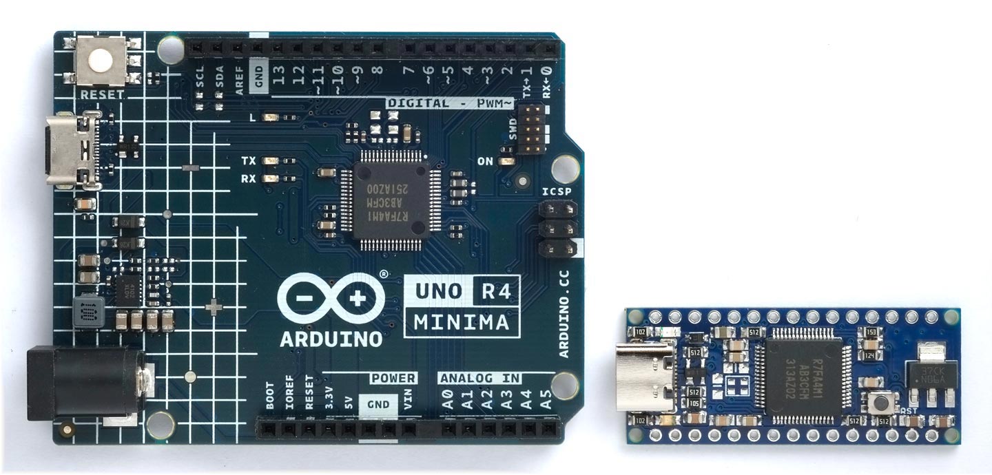
The RA4M1 Nano compared to its big brother, the Arduino Uno R4 Minima.
PCB design
I find designing PCBs quite relaxing, a bit like solving a Sudoku, but this one was a bit less relaxing than most because of the lack of space to route the tracks to the processor chip. I didn't want to go to a four-layer board, as these seem to cost about five times as much as a standard two-layer board. I routed the GND and VCC tracks last, and that proved to be the most difficult part. In the end I only got everything to fit by making a few small compromises, as described in the next section.
Differences from the Arduino Uno R4 Minima
I decided to keep closely to the circuit of the Arduino R4 Minima [6] so the RA4M1 Nano would work with the same Arduino core. However, I made a few simplifications to the circuit as follows:
- The original Arduino Uno R4 Minima uses a buck converter, based on an ISL85415 switching regulator, and this provides cool operation when running the board from input voltages of between 6V and 24V. I decided to use a simpler linear power supply based on an LM1117-5.0, which lets you run the board from between 7V and 12V.
- The USB_VBUS input (P407) detects the presence of the VBUS input, and the Arduino R4 Minima derives this from a voltage divider, designed to provide 3.3V from the 5V power supply. I couldn't see any reason not to just connect the 5V supply directly to the USB_VBUS input, saving three resistors, as the datasheet states that this input is 5V tolerant.
- The analogue input D20 (P500) is connected to 5V via a potential divider, to allow you to measure the 5V supply. The Arduino Uno R4 Minima uses a divider consisting 100kΩ and 13.7kΩ resistors, which means that you have to multiply the analogue reading by (100 + 13.7)/13.7 or 8.3. I decided to use more easily obtainable standard resistor values of 120kΩ and 15kΩ, which makes the factor (120 + 15)/15 or exactly 9.
- On the Arduino Uno R4 Minima the MD (BOOT) and NMI inputs are held high by separate 5.1kΩ resistors. I couldn't see any need to have two separate resistors, so have used a single shared resistor.
- To simplify the board layout I have only provided one of the two Reset pins provided on the original Arduino Nano.
- Finally, I have moved the A0 pin to the usual position of the A7 pin; it just wasn't possible to get the layout to work otherwise, and A6 and A7 aren't supported by the Arduino R4 Minima core anyway.
Powering the board
You can either power the board from the USB input, or from the VIN pin which can accept between between 7V and 12V, and uses the on-board regulator to provide 5V.
The 5V pin is a 5V output, to allow you to power other equipment. It can provide up to 500mA.
The 3V3 pin is a 3.3V output to allow you to power other equipment, using the RA4M1's on-chip regulator. It's available whether you power the board through USB or VIN. The maximum current is 50mA.
The circuit
Here's the circuit:
Circuit of the RA4M1 Nano board.
With USB-C the requirements for Electrostatic Discharge (ESD) protection are more stringent than for earlier versions of USB because the pin spacing is finer, and because there are potentially higher voltages on a USB-C cable. Fortunately you can get the necessary ESD protection diodes in a single low-cost four-pin package [7].
In addition, the USB-C shield is connected to GND via a 1MΩ resistor, and 4.7nF capacitor with a 1kV rating, to absorb ESD pulses from the shield. The two 5.1kΩ pull-down resistors on the CC pins indicate to the USB-C power source that the board accepts 5V at up to 3A.
Here's the parts list (click to expand):
► Parts list
Construction
I created a PCB in Eagle, and ordered a set of boards from PCBWay.
All the components are mounted on the top of the board. Because of the size of the processor chip there wasn't room to put the pin legends on the top of the board, so these are on the reverse, like on the Arduino Nano 33.
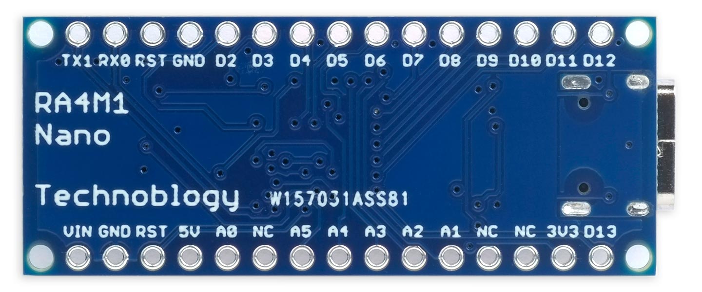
The reverse side of the RA4M1 board.
All the resistors, capacitors, and LEDs are 0805 size, and the processor chip is a 64-pin LQFP package. It might be possible to solder these with a fine-tipped soldering iron, but I used a Youyue 858D+ hot air gun at 275°C with Chip Quik SMD291AX10T3 solder paste.
Following the design of the Arduino Uno R4 Minima I provided a pad for a 2.5 x 2mm crystal and associated capacitors, but these should not be populated by default, and it will probably require a change to the Arduino core to enable the processor to use the crystal instead of the internal oscillator.
Testing the board
I recommend the following cautious procedure for initially testing the board:
- Apply +5V between VIN and GND while monitoring the current consumption. Anything above about 30mA indicates a possible short, so disconnect quickly and check for shorts between tracks on the board.
- Apply +5V between VIN and GND again, and check for +5V on the 5V pin, and +3.3V on the 3.3V pin.
- Connect the USB connector to 5V supply and check for +5V on the 5V pin, and +3.3V on the 3.3V pin again.
Installing the bootloader
To use the RA4M1 Nano board with the Arduino IDE via a USB cable you need to install a DFU bootloader on the board using the Renesas flash programmer. The procedure is as follows, as described in the Arduino Uno R4 Minima Cheat Sheet [8]:
- Locate the DFU bootloader file, which is provided as part of the Arduino Renesas UNO R4 Boards core. It is named dfu_minima.hex at:
…/Library/Arduino15/packages/arduino/hardware/renesas_uno/1.0.5/bootloaders/UNO_R4
or the equivalent on your installation.
- Download the Renesas flash programmer from their download page at:
Renesas Flash Programmer Download Page
The flash programmer is only available for Windows or Linux, and downloading it will require you to register an account at Renesas.
- Install and run the Renesas flash programmer.
- Connect the BOOT pin (the one between A0 and A5) to the GND pin on the RA4M1 board, and connect the board to your computer via a USB cable.
- In the Renesas flash programmer select File -> New Project….
The Create New Project dialog box is displayed:
- Set the Microcontroller to RA and provide a project name.
- Set the Tool to COM port, click Tool Details…, and select the COM port labelled USB Serial Device.
If no COM port is shown try resetting the RA4M1 Nano board.
- Click Connect.
The main program window is then displayed:
- On the Operation tab click Add/Remove Files… and select the dfu_minima.hex bootloader file.
- Click Start.
If the operation completes successfully the log panel should show Operation completed.
If there's a connection problem try reconnecting on the Connect Settings tab, and try again.
- Remove the link between the BOOT and GND pins.
Upload Blink to the board
You can test the board by uploading the Blink example to the board:
- Install the Arduino Renesas UNO R4 Boards core from Boards Manager.
- Choose Arduino UNO R4 Minima from the Arduino Renesas UNO R4 Boards option on the Tools menu.
- Select the USB port corresponding to the RA4M1 Nano board on the Port menu.
- Upload Blink from the Arduino IDE Examples menu.
If all is well the yellow built-in LED should flash.
Run uLisp on the board
As a more demanding test try running my Lisp interpreter for microcontrollers, uLisp, on the board. This uses most aspects of the Arduino core, and so provides a convenient way of testing features interactively from the Serial Monitor.
- Download the latest release of the ARM version of uLisp from: Download uLisp - ARM version.
- Upload it to the RA4M1 Nano board.
- Open the Serial Monitor from the Arduino IDE Tools menu.
You can now type Lisp commands at the uLisp prompt. For example, to calculate 2100:
> (expt 2 100)
1.26765e30
For more information about using uLisp on the RA4M1 Nano see: Arduino Uno R4 Boards - Arduino Uno R4 Minima.
Resources
The following Eagle files fix a couple of mistakes in the pin legends on my prototype, shown in the above photographs:
Get the Eagle files for the PCB here: https://github.com/technoblogy/ra4m1-nano-board.
Or order boards from OSH Park here: RA4M1 Nano Board.
Or order boards from PCBWay here: RA4M1 Nano Board.
Update
5th April 2024: Added information about powering the board, and the VIN, 5V, and 3V3 pins.
- ^ Arduino Uno R4 Minima on Arduino.cc.
- ^ Arduino Nano on Arduino.cc.
- ^ Arduino Nano 33 BLE on Arduino.cc.
- ^ Arduino Nano 33 IoT on Arduino.cc.
- ^ Arduino Nano ESP32 on Arduino.cc.
- ^ Arduino R4 Minima schematic on arduino.cc.
- ^ Nexperia PRTR5V0U2X Protection Diode datasheet.
- ^ Arduino Uno R4 Minima Cheat Sheet on arduino.cc.
blog comments powered by Disqus