MINIL Machine-Code Monitor
20th June 2014
This article describes a simple machine-code monitor designed to allow you to program a hypothetical processor called MINIL. It consists of a hexadecimal keypad, a four-digit seven-segment display capable of displaying four hexadecimal digits, an Enter button, and an ATtiny85 running the monitor program and MINIL interpreter:
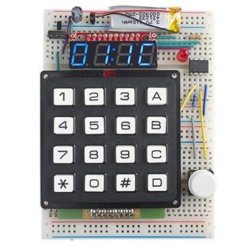
MINIL Machine-Code Monitor.
For an improved version of this project see Tiny Machine-Code Monitor.
Introduction
This project started from wanting to create a simple monitor that would enable beginners to learn about the concepts of instruction sets, machine code, and simple algorithms. I wanted to create something similar to the early microprocessor development kits such as the 6800-based Motorola D2 kit, the SC/MP-based Science of Cambridge Mk14, or the 6502-based KIM kit.
At first I thought of making the monitor show actual AVR machine code, but I soon realised that the AVR instruction set is far too powerful and not at all intuitive for the beginner. There is a large number of different instructions, and the instructions are difficult to decode into their op-code and operand fields, so a mnemonic assembler is almost essential.
I therefore decided to base my machine-code monitor on a hypothetical processor called MINIL (MINiature Interpreted Language) that I developed some time ago [1]. It has a very simple, symmetrical instruction set that you can remember without needing an assembler. The instructions are all single byte, and there is no memory addressing; all operations are between the eight 16-bit registers, called R0 to R7. In addition, the arithmetic is all binary-coded decimal, so you don't need to perform conversions between hexadecimal and decimal to verify that your program is giving the correct result.
The language is extremely primitive, but it can be used to write non-trivial programs; for example, you can write a program to find the highest prime factor of any number up to 9999 in just 17 bytes! It also illustrates many of the features of more advanced processors.
MINIL instruction set
Programs are entered into memory starting at location 0. All MINIL instructions consist of one byte, or two hex digits, and the instruction set is designed to be easy to learn so programs can be written directly in machine code without needing an assembler. There are three main types of instructions:
Loads
The load instructions copy the value in one register to another register (leaving the original unchanged). They consist of two hex digits, 0 to 7, specifying the destination and source registers.
Examples:
| Code | Mnemonic |
| 45 | R4 = R5 |
| 07 | R0 = R7 |
Jumps
The JZ (jump if zero) instructions are in the range 0x80 to 0xBF, and jump if the result of the previous DEC or ADD1 instruction was zero.
The JNZ (jump if non-zero) instructions are in the range 0xC0 to 0xFF, and jump if the result of the previous DEC or ADD1 instruction was not zero.
The bottom six bits of the jump instructions give the memory address that the jump will go to.
Examples:
| Code | Mnemonic |
| C3 | JNZ 3 |
| 84 | JZ 4 |
Special instructions
These all operate on a single register. The first hex digit is the register, 0 to 7, and the second hex digit specifies the operation:
A (ADD1) - Adds one to the specified register.
B (BRI) - Sets the brightness of the LED to the contents of the specified register, where 255 is maximum brightness and 0 is off.
C (CLR) - Clears the specified register.
D (DEC) - Decrements the specified register by 1.
E (ENT) - Enter number. It displays the contents of the specified register on the display. If Enter is pressed the program continues without altering the register's contents. Alternatively you can enter a number followed by Enter to put that into the register.
Examples:
| Code | Mnemonic |
| 1A | ADD1 R1 |
| 2B | BRI R2 |
| 3C | CLR R3 |
| 1D | DEC R1 |
| 0E | ENT R0 |
Unimplemented op codes
The unimplemented op codes, R8, R9, and RF (where R is a register 0 to 7) display an error, and can be used as breakpoints to debug programs.
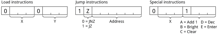
Summary
Here's a summary showing the bit format of the MINIL instructions:
Monitor
The MINIL monitor allows you to enter a program, run the program, or examine the registers. To enter the monitor at any time hold down the white Enter button for a second; the display prompts Go:.
You can then select one of the following monitor functions by pressing one of the keys on the keypad:
Enter program (*)
In this mode the display shows XX:YY where XX is the current location in hexadecimal, and YY is the byte in program memory at that location.
You can optionally type a new value in hexadecimal, using the keys on the keypad (with * for E and # forF). Pressing Enter then moves to the next location.
Run program (#)
This mode runs the program from location 0. While the program is running the display shows "....". When the program reaches an ENT instruction the display will show the contents of the specified register, and optionally allow you to enter a new value. Pressing Enter then resumes execution of the program.
Examine registers (0 - 7)
Displays the contents of the corresponding register R0 - R7, and optionally allows you to enter a value.
Here's an example of entering and running a program:
| What you press | Display shows |
| Hold down Enter | Go: |
| * (enter program) | 00:FF |
| 0, * | 00:0E |
| Enter | 01:FF |
| 0, D | 01:0D |
| Enter | 02:FF |
| C, 0 | 02:C0 |
| Enter | 03:FF |
| 8, 0 | 03:80 |
| Hold down Enter | Go: |
| # (run program) | 0000 |
| 0, 0, 1, 0 | 0010 |
| Enter | 0009 |
| Enter | 0008 |
The above sequence enters and runs a program to prompt for a number and then decrement it.
Note that if you've previously entered a program the memory locations will show the previous contents rather than FF.
MINIL programs
Because MINIL only provides the operations add one and decrement by one, a certain amount of ingenuity is needed to create useful programs, but it can be done. Here is a very simple MINIL program that prompts you to enter a number, and displays the number doubled, written in a pseudo assembler:
// Double a number
00 0E  Start: ENT  R0
01 10         R1 = R0
02 0A  Loop:  ADD1 R0
03 1D         DEC  R1
04 C2         JNZ  Loop
05 80         JZ   Start
For several more advanced programs, including making the LED pulsate in brightness, finding the highest factor of a number, and finding x^y, see Sample MINIL Programs. If you like a challenge, try writing programs to perform these functions before looking at the answers.
Circuit design
The MINIL machine-code monitor consists of a 16-key keypad, a four-digit serial 7-segment display, and a ATtiny85 microcontroller. Here's the circuit:
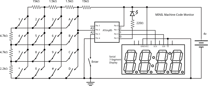
MINIL Machine-Code Monitor circuit.
For the display I chose Sparkfun's Serial 7-segment display [2], available in the UK from HobbyTronics [3], to make the interfacing easy and to allow me to use an ATtiny85 rather than a larger chip with more I/O lines. The ATtiny85 communicates with the display using its SPI interface, and needs two I/O lines; the SS line can be tied to ground since there's only one SPI device. The program uses Jack Christensen's tinySPI library [4] to communicate with the display.
Alternatively you could use an ATtiny84 with a 74HC595 to drive a 4-digit 7-segment display module directly.
For the keypad I used a low-cost Multicomp 4x4 keypad, which is available from Farnell [5] or on eBay. It is interfaced to a single analogue input using a resistor ladder under the keypad to generate a different voltage for each button, as described in my earlier post One Input Keypad Interface:
A separate button is used for the Enter key, and this uses a separate I/O input. Finally, an LED is attached to the remaining I/O pin, and the brightness of this can be controlled from the MINIL program using PWM.
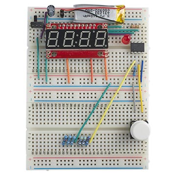
The whole circuit is powered by a 3.7V LIPO cell, and was constructed on two mini-breadboards joined together.
I developed the machine-code monitor using the Arduino IDE and uploaded it to the ATtiny85 using SparkFun's Tiny AVR Programmer [6] (available in the UK from Proto-PIC [7]). It could equally well be run on an Arduino, or any of the other AVR chips.
The user's program is stored in the EEPROM on the ATtiny85, so it are retained even when the power is switched off. The 512 bytes are plenty for simple MINIL programs.
MINIL interpreter
The MINIL interpreter is implemented by the Run() routine. This reads the next machine-code instruction from the corresponding EEPROM location, and then branches to one of a number of if statements to execute the different types of instruction.
// MINIL Interpreter - Run the user's program
void Run() {
  long Word;
  int Sign;
  unsigned int PC, Value, Jump;
  char Inst, Reg, Special, Type;
  boolean ZeroFlag = false;
  PC = 0;
  DisplayRunning();
  do {
    // Get next Instruction
    Inst = EEPROM.read(PC++);
    Type = Inst & 0x88;
    Reg = (Inst >> 4) & 0x07;
    if ((Inst & 0x80) != 0) {
      // Jump instructions
      Jump = Inst & 0x3F;
      if (((Inst & 0x40) == 0) == ZeroFlag) PC = Jump;
    } else if (Type == 0) {
      // Load Instruction
      Register[Reg] = Register[Inst & 0x07];
    } else if (Type == 0x08) {
      // Special Instructions
      Special = Inst & 0x0F;
      Value = Register[Reg];
      if ((Special == 0x0A) || (Special == 0x0D)) {
        // Decrement or Add1 and convert to BCD
        if (Special == 0x0A) Sign = 1; else Sign = -1;
        Value = Value + Sign;
        for (int i=0; i<16; i=i+4) {
          // Binary-coded decimal correction - must be a neater way!
          if ((Value & (unsigned int)(0xF<<i)) > (unsigned int)(0x9<<i)) {
            Value = Value + Sign * (unsigned int)(0x6<<i);
          }
        }
        Register[Reg] = Value;
        ZeroFlag = (Value == 0);
      } else if (Special == 0x0B) {
        // Brightness - Convert value from BCD
        Value = ((Value>>8) & 0x0F)*100 + ((Value>>4) & 0x0F)*10 + (Value & 0x0F);
        analogWrite(LED,255-Value);
      } else if (Special == 0x0C) {
        // Clear
        Register[Reg] = 0;
      } else if (Special == 0x0E) {
        // Display and enter
        Display(Value);
        do {
          Word = GetData(4);
          if (Word != -1) Register[Reg] = Word;
        } while (Word != -1);
        LongPress();
        DisplayRunning();
      } else {
        // Invalid special instruction
        DisplayError();
        DisplayTwo(Special);
        do ; while (!ReadButton());
      }
    }
  } while (!ReadButton());
}
You could modify this to add instructions in the positions of the unimplemented op codes, or change the operation of the existing instructions. For example, you could create a robot control language, or a graphical plotting language like Logo.
Most of the rest of the program consists of routines to read values from the keypad, and format the different displays on the 7-segment display. You can get the full listing here: MINIL Machine-Code Monitor Program.
A challenge
Write a MINIL program to find the number of combinations of n things r at a time, ncr. For example, it should give ncr(12, 7) = 792. I'll give a solution in a future blog post.
- ^ MINIL Interpreter in "Mk14 Further Application Programs" by David Johnson-Davies, pp. 18-23, published by Science of Cambridge Ltd, Cambridge, UK.
- ^ 7-Segment Serial Display on Sparkfun.
- ^ 7-Segment Serial Display on HobbyTronics.
- ^ Arduino TinySPI Library on GitHub.
- ^ Multicomp 4x4 Keypad on Farnell.
- ^ Tiny AVR Programmer on SparkFun
- ^ Tiny AVR Programmer on Proto-PIC
blog comments powered by Disqus