Tiny Colour Watch
15th January 2018
This article describes a minimalist ATtiny85-based watch using 12 APA102 RGB LEDs, arranged like a clock face, to show the time analogue-style. It shows the time to the nearest second, and the positions of the hour, minute, and second hands are displayed in blue, red, and green respectively. Intermediate times are shown by the relative brightness of two adjacent LEDs:
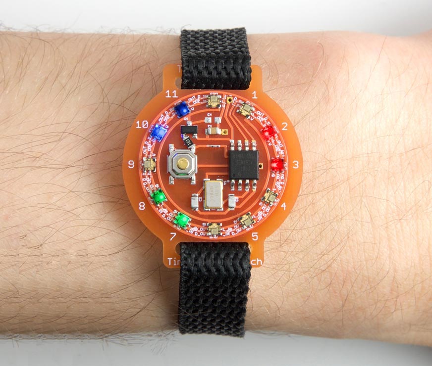
The Tiny Colour Watch based on an ATtiny85; it's twelve minutes past ten and 37 seconds.
To show the time you press the button on the watch face; the display is blanked after 15 seconds to save the battery. The ATtiny85 is clocked by a crystal, ensuring that the time is accurate to within a few seconds a month.
Introduction
This is the third of my LED-based watch designs. My earlier Tiny Time 2 Watch used monochrome LEDs, and distinguished between the hour and minute hands by flashing the minutes LED. I thought I had taken the Tiny Time watch concept as far as it could go until I read about the APA102 LEDs, full colour LEDs in a 2020 package that cost under $5 for a dozen. You can control them using a two-wire serial interface, and daisy-chain a virtually unlimited number of them together, with individual control over the colour and brightness of each LED.
I realised that this would allow me to design an ATtiny85-based watch, using two I/O lines to control the 12 RGB LEDs, two I/O lines to connect to an external crystal, and one I/O line free to connect to a pushbutton to display the time. Because the timing is performed by the ATtiny85 there's no need for an RTC chip.
Telling the time
The watch hands are represented by different colour LEDs. I chose blue for the hour hand, red for the minute hand, and green for the second hand.
The position of each hand is represented by the proportional brightness of two adjacent LEDs. For example, when the minute hand is at five past the hour LED 1 is at 100% red and LED 2 is off. At six minutes past the hour LED 1 is 80% red and LED 2 is 20% red, and so on until at ten past the hour LED 1 is off and LED 2 is 100% red.
The circuit
Here's the circuit of the Tiny Colour Watch:
The circuit looks more complicated than it actually is, because the LEDs are simply in a daisy-chain; I've arranged them in a circle to reflect how they're laid out on the watch face.
The LEDs are APA102-2020 serial-controlled RGB LEDs. I bought mine from Maleectronic on Tindie [1], or they are also available from AliExpress [2]. Although they are specified as needing a 5V supply, I found they work reliably down to 3V, although at this voltage the blue LEDs are slightly less bright than the red and green LEDs.
The resistor and capacitors are all 0805 size components.
For the crystal I used an ABM3B 8MHz SMD type, which needs 10pF capacitors [3], although any 8MHz SMD crystal should be suitable. The button is a miniature SMD push button available from Sparkfun [4], available from Proto-PIC in the UK [5].
Although the watch will work with a CR2032 coin cell, I recommend using an LIR2032 rechargeable lithium coin cell; as well as being more economical, it gives a slightly higher voltage of 3.7V rather than the CR2032's 3.0V, which makes the blue LEDs brighter [6]. If you do use a CR2032 you might want to use the blue LEDs for the seconds, so their brightness is not so important. The battery fits in an SMD 20mm coin cell holder available from Sparkfun [7], or from Proto-PIC in the UK [8].
After trying out a prototype I realised that the APA102 LEDs draw about 11mA even when all the LEDs are turned off, which would limit the watch's battery life. I therefore added a P-type MOSFET as a high-side power switch, to allow the processor to turn off power to the LEDs when the display is off. There wasn't a spare I/O pin I could use to drive the MOSFET, but fortunately I could make the switch input double up as the power enable; pressing the switch both enables the display, and generates a signal to wake up the processor.
The main criterion for the MOSFET is that it should have a low turn-on voltage, VGS, of under 2.0V. It should also be able to handle the current drawn by the LEDs; this is 20mA with a typical time display. I chose the Fairchild FDN306P, with a VGS of 1.8V, which is in an SOT-23 package [9].
In my first prototype I didn't include the 100Ω resistor in the gate of the MOSFET, and I couldn't understand why the ATtiny85 reset every time I pressed the button. After a bit of research I realised that the gate capacitance can cause a large current spike when the MOSFET switches; the solution is to add a small series resistor.
► Parts list
Construction
I designed the board in Eagle and sent it to Ragworm in the UK for fabrication [10]. Here's the layout of the latest version (from the OSH Park preview):
There's a link to the Eagle files at the end of the article if you want to make yourself a board.
I built the watch on a small printed circuit board, using SMD components, with all the components apart from the battery holder soldered to one side of the board:
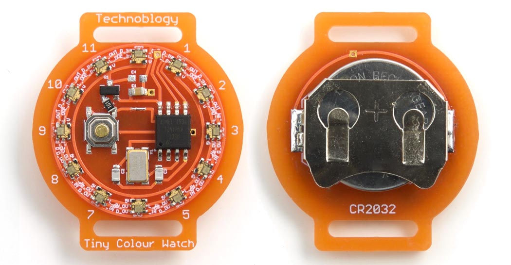
The completed Tiny Colour Watch circuit board.
The AP102-2020 LEDs are pretty tricky to solder, and I don't think it would be possible with a normal soldering iron. The procedure I used was to mount one LED at a time by applying a small blob of solder paste to each pad with the tip of a pin, and I then gently placed the LED in position with a pair of tweezers. I then heated up the LED with a Youyue 858D+ hot air gun set to 250°C until I could see the molten solder glistening around the base of the LED. Once the solder melts, surface tension tends to centre the LED correctly on the pads, so the initial placement isn't too critical.
Once all the SMD components were soldered on the front of the board I finally soldered the battery holder onto the back of the board using a conventional soldering iron.
The program
Controlling the LEDs
The APA102s are controlled using a two-wire SPI signal. The chips are daisychained together, with each chip generating the data and clock for the next chip:
The data consists of:
- A start frame of 32 '0' bits.
- A 32-bit frame for each LED, specifying the brightness and colour.
- An end frame of 32 '1' bits.
The 32-bit frame for each LED consists of:
- Three '1' bits.
- Five bits specifying the brightness, MSB first.
- Eight bits specifying the blue component, MSB first.
- Eight bits specifying the green component, MSB first.
- Eight bits specifying the red component, MSB first.
Tim Böscke has analysed the APA102 and determined that the end frame actually only needs to contain a number of bits equal to half the number of APA102s in the chain [11], so with 12 LEDs we only need 6 bits.
The state of the 12 LEDs is specified by a 12x4 array, Display[][], defined as folows:
uint8_t Display[12][4];
The four elements specify the brightness, blue, green, and red components of each LED respectively. The routine ClearBuffer() clears all the elements to zero, to give blank displays:
void ClearBuffer () {
  for (int d=0; d<12; d++) {
    for (int c=0; c<4; c++) Display[d][c] = 0;
  }
}
The following routine, Write(), writes a single display definition to the chain of displays:
void Write (uint8_t c) {
  int i=0x80;
  while (i) {
    if (c & i) PORTB = PORTB | 1<<Data;  // set Data high
    else PORTB = PORTB & ~(1<<Data);     // set Data low
    PINB = 1<<Clk;                       // set Clk high
    i = i>>1;
    PINB = 1<<Clk;                       // set Clk low
  }
}
The routine UpdateDisplay() calls Write() to update all 12 LEDs from the Display[][] buffer:
void UpdateDisplay () {
  for (int d=0; d<4; d++) Write(0);      // Start frame
  for (int d=0; d<12; d++) {
    Write(Display[d][0] | 0xE0);         // Brightness 0-31
    Write(Display[d][1]);                // Blue
    Write(Display[d][2]);                // Green
    Write(Display[d][3]);                // Red
  }
  Write(0xFF);                           // End frame
}
Timekeeping
The watch uses the 8MHz crystal in conjunction with Timer/Counter0 to keep track of the time. This is set up in Setup() to generate a compare match interrupt at 125Hz:
  TCCR0A = 2<<WGM00;               // CTC mode; count up to OCR0A
  TCCR0B = 0<<WGM02 | 4<<CS00;     // /256 = 31250
  OCR0A = 249;                     // /250 -> 125Hz
  TIMSK = 1<<OCIE0A;               // Enable compare match interrupt
The interrupt service routine simply increments a Seconds counter every 125 Ticks:
ISR(TIM0_COMPA_vect) {
  Ticks++;
  if (Ticks == Tickspersec) {Ticks = 0; Seconds++; }
}
To read the number of seconds we use a routine Secs() to ensure that interrupts are disabled around the call:
unsigned long Secs() {
  cli(); unsigned long s = Seconds; sei();
  return s;
}
Displaying a watch hand
The brightness and position of each watch hand is handled by the routine Hand(), which takes a number between 0 and 59 to specify the position around the dial, and a colour, and sets up the brightness of two adjacent LEDs as appropriate:
void Hand (int Unit, int Colour) {
  int to = Unit/5;
  int from = (to+11)%12;
  int count = Unit%5;
  Display[from][Bright] = Brightness;
  Display[from][Colour] = Level(count);
  Display[to][Bright] = Brightness;
  Display[to][Colour] = Level(5-count);
}
The time is actually displayed by the routine ShowTime(). The main part of this reads the time, in seconds, and then displays the hour, minute, and second hands in the correct positions:
unsigned long Now = Secs();
int secs = Now%60;
int mins = (unsigned long)(Now/12)%60;
int hours = (unsigned long)(Now/720)%60;
ClearBuffer();
Hand(hours, Hour);
Hand(mins, Minute);
Hand(secs, Second);
UpdateDisplay();
It repeats this every second until the display is blanked, after the specified timeout interval.
Setting the time
When you first apply power to the watch it runs SetTime() which allows you to set the time to the nearest second. It works as follows: wait until the current time is an exact number of minutes, and insert the battery. The watch will then start from 12:00, stepping through the display, advancing one minute every fifth of a second. When the watch shows the time you inserted the battery, hold down the button until the green seconds LEDs appear. The watch will account for the additional time it took you to set the time, and display the correct time accurate to the nearest second.
Minimising power consumption
To maximise the battery life the program slows down the processor clock by a factor of 256, whenever the display is blanked, from the normal 8MHz to 31.250kHz.
The following instructions slow down the clock:
  CLKPR = 1<<CLKPCE;               // Enable clock change
  CLKPR = 8<<CLKPS0;               // Divide clock by 256 to 31250 Hz
  TCCR0B = 0<<WGM02 | 1<<CS00;     // /1 = 31250
The last instruction reduces the Timer/Counter0 prescaler to accomodate for the change in clock speed. To restore the clock to 8MHz the instructions are:
  CLKPR = 1<<CLKPCE;               // Enable clock change
  CLKPR = 0<<CLKPS0;               // Divide clock by 1 to give 8 MHz
  TCCR0B = 0<<WGM02 | 4<<CS00;     // /256 = 31250
In addition, to save power the ADC and unused clocks are disabled, and the processor is switched to idle mode when the display is blanked:
  ADCSRA &= ~(1<<ADEN);            // Disable ADC
  PRR = 1<<PRUSI | 1<<PRADC | 1<<PRTIM1;  // Turn off clocks to unused peripherals
  set_sleep_mode(SLEEP_MODE_IDLE);
The processor is woken up from idle mode at each COMPA interrupt. The pushbutton is checked in loop(); if it is being pressed the time is displayed; otherwise the processor is put back to sleep:
void loop () {
  if ((PINB & 1<<Enable) == 0) ShowTime();
  sleep_enable();
  sleep_cpu();
}
With the display blanked the current consumption is about 0.24mA at 3V. A typical CR2032 battery has a capacity of 225mAH, so it should last over a month.
Compiling the program
I compiled the program using Spence Konde's ATTiny Core [12]. Select the ATtiny x5 series option under the ATtinyCore heading on the Boards menu. Then choose Timer 1 Clock: CPU, B.O.D. Disabled, ATtiny85, 8 MHz (external) from the subsequent menus.
I connected to the ATtiny85 using a clip that fitted to the top of the chip [13], using the Sparkfun Tiny AVR Programmer [14]. Choose Burn Bootloader to set the fuses appropriately, if necessary, and then choose Upload to upload the program.
Here's the whole Tiny Colour Watch program: Tiny Colour Watch Program.
Alternatively, get it on GitHub here together with the Eagle files for the PCB: Tiny Colour Watch on GitHub.
Or order a board from OSH Park here: Tiny Colour Watch Board.
Update
13th February 2019: Due to the popularity of this project I've added a parts list, to help in sourcing the components.
9th February 2020: I've added a section in the Introduction to explain how the watch displays the time.
- ^ APA102-2020 RGB LED from Maleetronic on Tindie.
- ^ DotStar Micro LEDs APA102 2020 from Jiufeng Lighting on AliExpress.
- ^ ABM3B 8.000MHz Abracon Crystal SMD on Farnell.co.uk.
- ^ Mini Push Button Switch - SMD on SparkFun.
- ^ Mini Push Button Switch (SMD) on Proto-PIC.
- ^ Button cell (rechargeable) LIR2032 on Conrad Electronic.
- ^ Coin Cell Battery Holder - 20mm (SMD) on SparkFun.
- ^ Coin Cell Battery Holder - 20mm (SMD) on Proto-PIC.
- ^ Fairchild FDN306P P-channel MOSFET on RS-Online.
- ^ Ragworm PC prototyping service.
- ^ Understanding the APA102 "Superled" on Tim's Blog.
- ^ ATTinyCore on GitHub.
- ^ IC test Clip - SOIC 8-pin on SparkFun.
- ^ Tiny AVR Programmer on Sparkfun.
blog comments powered by Disqus