Lisp Badge [Updated]
10th January 2019
This is a self-contained computer with its own display and keyboard, based on an ATmega1284, that you can program in the high-level language Lisp:
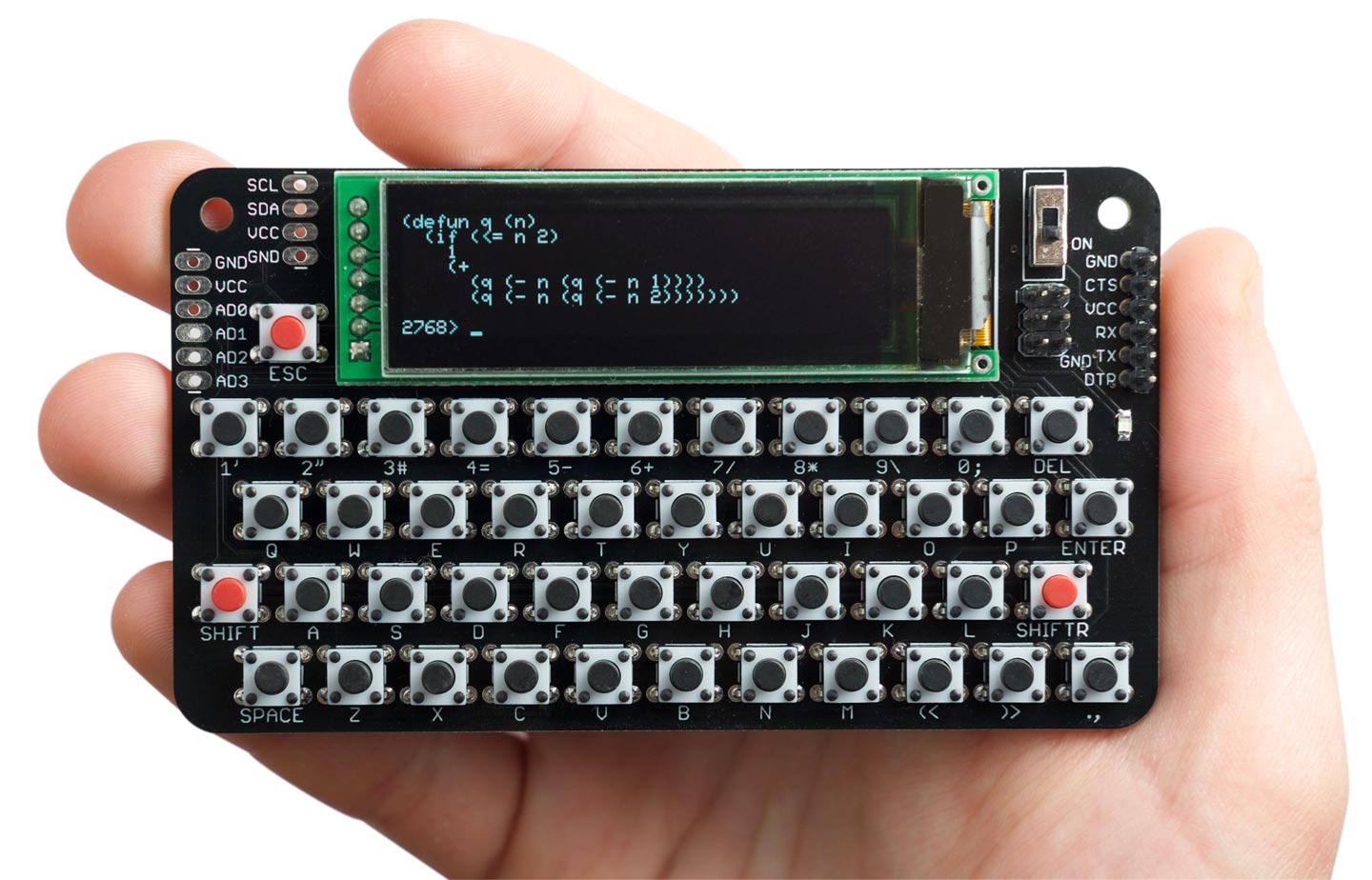
The Lisp Badge, a computer programmed in Lisp with a self-contained keyboard and display.
You can use it to run programs that interface to components such as LEDs and push-buttons via the I/O pins, read the analogue inputs, and operate external devices via the I2C and SPI interfaces. It has a greyscale OLED display that gives 8 lines of 42 characters, and an integrated 45-key keyboard optimised for Lisp.
Introduction
My earlier Tiny Lisp Computer 2 PCB was a board running Lisp that was just 3.25" x 1.5", but although it had an integrated display, it needed an external keyboard.
I was inspired to make this new version when I saw Voja Antonic's Belgrade Badge, a self-contained BASIC computer with an integrated keyboard and display designed for the Hackaday Belgrade conference in July 2018 [1].
The keyboard is based on tactile pushbuttons that are available for under 6 pence/cents each. I decided to keep the board as compact as possible by providing only the keys needed to program in uLisp, which meant departing from a standard keyboard layout. One benefit of this is that the keys you use a lot when entering Lisp programs, the parentheses '(' and ')', are on two dedicated keys on the bottom row of the keyboard.
For the display I chose a very nice greyscale OLED display with a resolution of 256 x 64 available on AliExpress [2], which gives a text display of 42 x 8 characters. It's slightly more expensive than the usual 128 x 64 displays, but is perfect for this project.
The Lisp badge is based on an ATmega1284P, which I think is the best ATmega processor for running uLisp as it provides 16 Kbytes of RAM, more than any other ATmega chip. This chip drives the display, scans the keyboard, and handles the Lisp interpreter, without needing any other active devices; the circuit uses every pin on the 44-pin chip.
I designed the Lisp Badge to be powered by an AAA-sized 3.7V LiPO battery, and the processor runs with a 16MHz crystal clock. According to the Atmel datasheet the ATmega1284 needs 3.825V to work at 16MHz, but I haven't had any problems; if you prefer to err on the safe side you could use a 12MHz crystal, which should be fine down to 3.15V.
Here's the full specification:
Lisp Badge – Specification
Size: 107mm x 61mm (4.2" x 2.4").
Display: 42 characters x 8 lines.
Keyboard: Integrated 45-key keyboard providing upper and lower-case characters, digits, and the symbols required by uLisp. The ESC key provides an alternative to entering '~' to escape from a running program.
Memory available: 2816 Lisp cells (11264 bytes).
EEPROM: 1024 Lisp cells (4096 bytes), allows you to save the Lisp workspace using save-image.
Processor: ATmega1284P
Clock speed: 16 MHz.
Current consumption: Approx. 20 mA.
Language
uLisp, a subset of Common Lisp, with 122 Lisp functions and special forms. For a full definition see uLisp Language Reference.
The language includes two extensions, plot and plot3d, for plotting graphs and 3d functions.
uLisp also includes an AVR assembler which allows you to generate and run machine-code functions, written in AVR mnemonics, using an assembler written in Lisp.
Types supported: list, symbol, integer, character, string, and stream.
An integer is a sequence of digits, optionally prefixed with "+" or "-". Integers can be between -32768 and 32767. You can enter numbers in hexadecimal, octal, or binary with the notations #x2A, #o52, or #b101010, all of which represent 42.
User-defined symbol names can have arbitrary names. Any sequence that isn't an integer can be used as a symbol; so, for example, 12a is a valid symbol.
There is one namespace for functions and variables; in other words, you cannot use the same name for a function and a variable.
Includes a mark and sweep garbage collector. Garbage collection takes 5 msec.
Interfaces
These interfaces are brought to headers at the edge of the Lisp Badge board. The numbers in brackets refer to Arduino pin numbers:
- Four analogue input pins using analogread: A0 to A3 (24 to 27) plus VCC and GND.
- Two analogue outputs using analogwrite: MISO (6), and SCK (7).
- Digital input and output using pinmode, digitalread, and digitalwrite: MOSI (5), MISO (6), SCK (7), RX0 (8), TX0 (9), SCL (16), SDA (17), and A0 to A3 (24 to 27)
- I2C interface using with-i2c and restart-i2c: SCL (16) and SDA (17).
- SPI interface using with-spi: MOSI (5), MISO (6), and SCK (7).
- Serial interface (FTDI) using with-serial: RX0 (8) and TX0 (9).
SCK (7) is connected to an LED on the front panel. This is an analogue output pin, so you can vary the brightness of the LED.
Entering programs
You can enter commands and programs by typing them at the keyboard, and pressing ENTER. A keyboard buffer is provided that buffers a full screen of text, and you can use the DEL key to delete characters and correct typing mistakes. The editor includes parenthesis matching which automatically highlights matching brackets in grey as you type in a program. This makes it much easier to enter a program correctly, and is especially helpful in telling you how many closing brackets to type at the end of defining a function.
Typing on the tactile buttons isn't particularly easy, but you can also connect the Lisp Badge to a computer by plugging a 3.3V FTDI USB-to-serial converter onto the FTDI connector on the top right of the Lisp Badge, and then connecting this to the computer using a USB cable. You can then use the Serial Monitor in the Arduino IDE to enter and edit programs as described in Using uLisp.
I used the 3.3V FTDI Basic Breakout from Sparkfun [3]. When using it with the Lisp Badge it powers the Lisp Badge, and so the battery should be removed or switched off.
Plot function
I've added a plot3d function, to allow 3D function plotting on the display. You call it with a function of two arguments, x and y, and it calculates the function for every (x, y) point between (0, 0) and (127, 63) and plots the greyscale of the value returned, between 0 and 15:
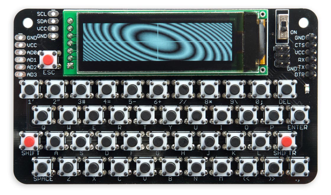
Demonstration of the Lisp 3D plotting function.
There's also a 2D plot function that will plot up to four 2D functions, with optional axes.
For details see Plotting extensions.
The display
The display is a greyscale OLED display with 16 grey levels and a resolution of 256 x 64. It's based on an SH1122 driver chip [4]. To test out the display I built a terminal program, which I've described in an earlier article: Tiny Terminal 2.
After designing the Lisp Badge PCB in Eagle I ordered a second display from the same AliExpress supplier, as a spare, and was shocked to discover that it was a new Version 1.1 of the board with the order of the pins reversed, so it would no longer work in my PCB!
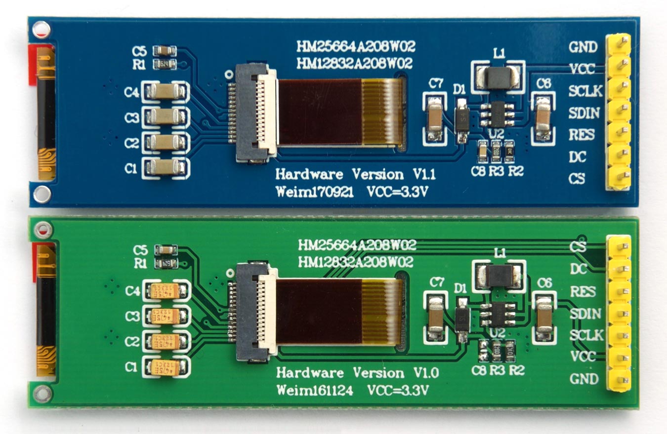
The two alternative versions of the 256x64 OLED display.
The Eagle files I've provided on GitHub are for the V1.0 display. I've made a second version of the PCB for the Version 1.1 display; contact me if you need this for use with a V1.1 display.
The circuit
Here's the main part of the circuit:
Circuit of the Lisp Badge, based on an ATmega1284P microcontroller.
The keyboard arranges the keys in a matrix of four rows and 11 columns:
The circuit of the Lisp Badge keyboard matrix.
► Parts list
Construction
I created a PCB in Eagle, and ordered a set of boards from PCBWay. I chose black PCBs as the white screening shows up well against black.
Most of the components, apart from the pushbuttons and display, are mounted on the back of the board:
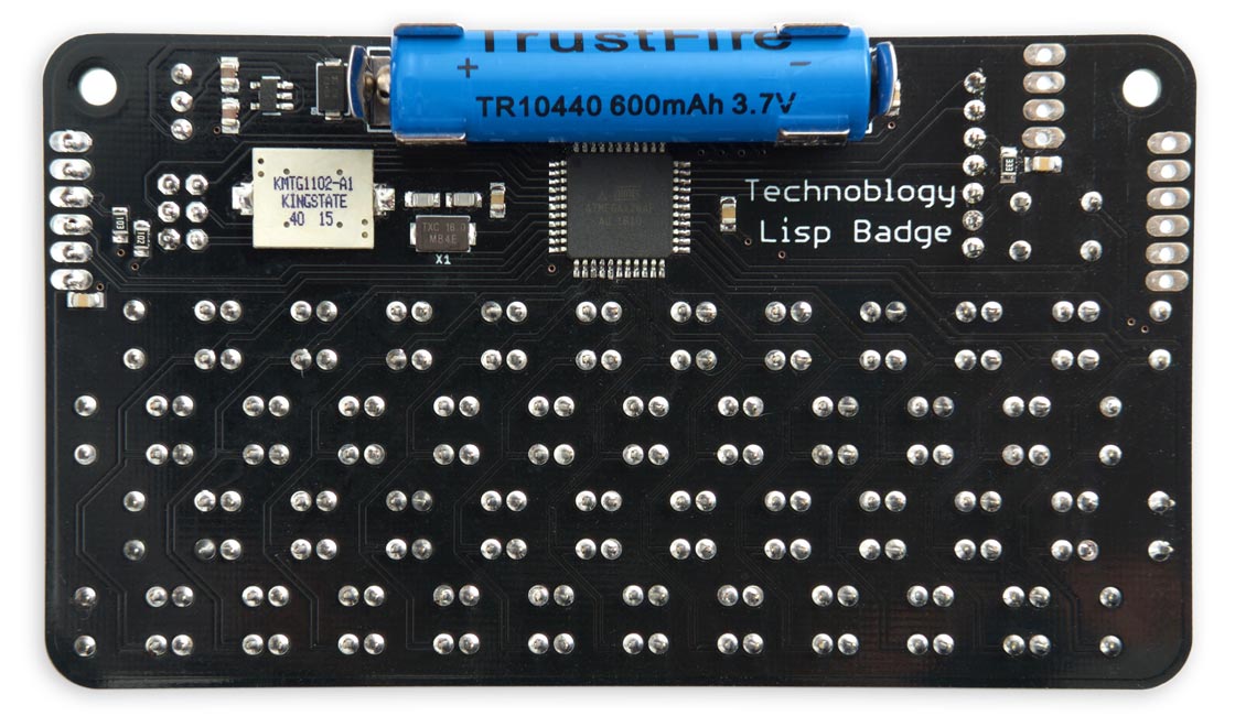
The reverse side of the Lisp Badge printed circuit board.
All the components are SMD apart from the pushbuttons, which are through-hole. I chose through-hole pushbuttons because (a) they're cheaper, (b) they are easier to solder by hand, and (c) the holes ensure that they line up perfectly. The downside is that it makes the back of the PCB prickly, but you could solve that with a small case, or a large self-adhesive foam pad.
The PCB uses 0805 resistors, capacitors, and an LED. I used a Youyue 858D+ hot air gun at 250°C to solder the SMD components, but with care it should be possible to use a fine-tipped soldering iron. The PCB is designed for a two-pad SMD crystal. I used an Abracon ABM7 16.000MHz type.
The display is held in place with a double-sided self-adhesive foam pad, and then soldered to the board with seven header pins, but I recommend leaving the display uninstalled until you have uploaded the bootloader; see below.
The program
The Lisp Badge program is based on the code for the AVR version of uLisp Version 2.5 (see Download uLisp), with the addition of routines to handle the display and keyboard, and the plot extensions.
The display routine is essentially the same as in my earlier project Tiny Terminal 2. It uses character set definitions stored in program memory to generate the characters, and hardware scrolling to scroll the display when the cursor moves below the bottom line of the display. The parenthesis highlighting works in the same way as in my Tiny Lisp Computer 2.
The keyboard uses the ATmega1284's Timer/Counter2 to generate an overflow interrupt at about 2kHz. Each call of the overflow interrupt service routine takes the next column low in the keyboard matrix, and it then tests to see if any of the four row inputs has been pulled low by the pressing of a pushbutton. If so, the button's position is looked up in a key table to translate it to the ASCII code of the key. This also takes into account the state of the SHIFT keys, which are connected to a dedicated input.
Installing a bootloader
To program the Lisp Badge I now recommend using MCUdude's MightyCore on GitHub.
The first step is to install a bootloader using an ISP programmer. The Optiboot bootloader provided with MightyCore also supports writing to flash, which uLisp now uses for save-image and the AVR assembler.
Because the display is only tolerant of 3.3V you should either use an ISP programmer that supplies 3.3V, or do this before connecting the OLED display to the board. I used a USBasp ISP programmer set to the 3.3V setting.
Choose the ATmega1284 option under the MightyCore heading on the Board option on the Tools menu. Check that the subsequent options are set as follows (ignore any other options):
Clock: "External 16MHz"
BOD: "BOD 2.7V"
Compiler LTO: "LTO enabled"
Variant: "1284P"
Pinout: "Standard pinout"
Bootloader: "Yes (UART0)"
Set the Programmer option as appropriate for the ISP programmer you are using. Then choose Burn Bootloader.
Uploading the Lisp Badge code
The next step is to install the Lisp Badge code, using an 3.3V FTDI USB-to-serial converter plugged into the FTDI connector on the PCB. I used the SparkFun FTDI Basic Breakout [5].
Leave the MegaCore options set as described above, and choose the USB port from the Port submenu. Then choose Upload from the Sketch menu to upload uLisp.
Resources
Get the latest Lisp Badge source from GitHub, together with the Eagle files for the PCB so you can make yourself a board, at: Lisp Badge.
Or order a board from OSH Park here: Lisp Badge Board.
Or order a board from PCBWay here: Lisp Badge Board.
For more information about the Lisp Badge, and some example programs demonstrating its sound and graphics features, see Lisp Badge.
Updates
11th January 2019: Added a brief description of the program.
12th January 2019: Added current consumption to the specification.
13th January 2019: Corrected 5V in the circuit diagram to 3.3V.
8th March 2019: Corrected the instructions for installing a bootloader.
26th May 2019: I've just uploaded a new version of the Lisp Badge source to GitHub, updated to use the latest version of uLisp, version 2.7.
10th July 2020: The Lisp Badge source was updated to uLisp Version 3.3a.
4th April 2021: The Lisp Badge source has been updated to uLisp Version 3.6, and I've updated the installation instructions to describe using MCUdude's MightyCore, which is required for the new save-image and AVR assembler features.
- ^ Badge for Hackaday Conference 2018 in Belgrade on Hackaday.
- ^ 2.08 inch 7P SPI White OLED Screen Module on Aliexpress.
- ^ FTDI Basic Breakout – 3.3V - on Sparkfun.
- ^ SH1122 datasheet on DisplayFuture.
- ^ FTDI Basic Breakout 3.3V on SparkFun.
blog comments powered by Disqus