Programmable Signal Generator
14th June 2018
This project describes a simple digital signal generator capable of generating a square wave from 1kHz to 68MHz with an accuracy of 1.1%. You enter the frequency on a numeric keypad, and the frequency is displayed on an I2C 128x32 OLED display:
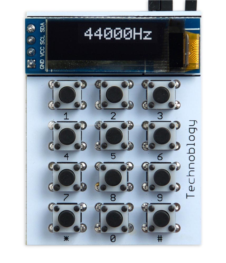
The Programmable Signal Generator can generate a square wave from 1kHz to 68MHz.
The circuit is based on the Linear Technology LTC6904 [1] I2C programmable oscillator, and it's controlled by an ATtiny85.
Introduction
I needed a signal generator for other projects I'm working on, such as testing processors running with different external clock frequencies, and because I needed frequencies over 20MHz my earlier Tiny Function Generator wasn't suitable. I therefore chose the interesting LTC6904 programmable oscillator which is available from Farnell [2] or RS-Online [3].
I initially thought of displaying the frequency on two 4-digit seven-segment LED displays, which would require at least 11 pins to drive them and so need an ATtiny2313 or larger; see Driving LED Displays with Fewer I/O Lines. However, the thought of wiring up the displays on a prototyping board soon put me off the idea, and nowadays an I2C OLED display is a much more attractive option; in fact I think seven-segment LED displays have almost had their day. Combined with my One Input Keypad Interface I was able to use an ATtiny85 as the controller for the whole project, and wire up a prototype on a breadboard in under an hour.
The LTC6904
The LTC6904 programmable oscillator is an interesting chip. You program the frequency via I2C using two 8-bit registers which provide a 4-bit octave, OCT, and a 10-bit DAC value. The frequency is specified by:
I'm not sure why they chose the constant 2078. For a desired frequency you need to calculate the OCT and DAC values, and so it's useful having an ATtiny85 available to do the arithmetic.
My program works as follows: you enter the frequency you want, in Hz, as a sequence of up to eight digits, and press *. The display then shows the nearest frequency that the chip can generate, and generates the square wave on the output. Pressing # at any time clears the current input.
The circuit
The circuit takes advantage of my One Input Keypad Interface to read the keyboard using a single analogue input on the ATtiny85. It uses a two-wire I2C interface to connect to the OLED display and the LTC6904 programmable oscillator, leaving two I/O lines on the ATtiny85 unused:
The circuit of the Programmable Signal Generator.
Construction
I built a first version of the circuit on a prototyping board, using an off-the-shelf keypad [4].
For the final version I designed a board in Eagle and sent it to PCBWay for fabrication [5]. There's a link to the Eagle files at the end of the article if you want to make yourself a board.
The circuit board is designed around low-cost through-hole tactile buttons that you can get from suppliers for as little as 4 cents/pence each [6], or less from Banggood [7]. The display is an OLED 128x32 I2C display module using the SSD1306 driver. I used a low-cost module from AliExpress [8] held in place with a double-sided self-adhesive foam pad. The PCB also accommodates Adafruit's version [9].
To keep the board as compact as possible the other components are surface mounted on the reverse of the board:
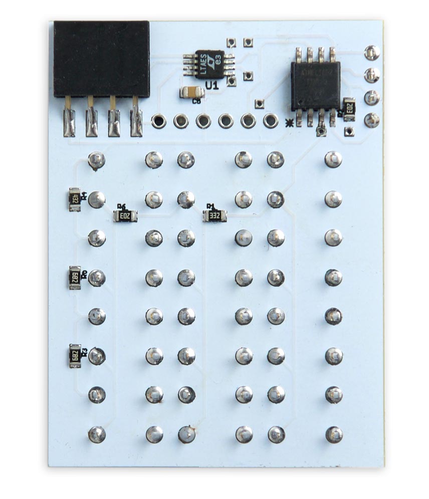
The back of the Programmable Signal Generator PCB showing the surface-mount components.
The power supply and oscillator output are accessed via a 4-way connector at the edge of the board.
The program
The program consists of three main sections to handle the keyboard, display, and interface to the programmable oscillator chip.
The keyboard interface is based on my earlier One Input Keypad Interface, which uses carefully chosen resistors to give a different voltage at an analogue input for each key on the keypad.
The display interface uses the same routines as my earlier Tiny Function Generator, which used the same I2C OLED display. The frequency is plotted using double-sized characters; this gives a maximum of 10 characters on the line, which is just sufficient for the 8-digit frequency and the "Hz" suffix.
Programmable oscillator interface
When you type in a target frequency, the CalculateParameters() routine calculates the DAC and OCT values that need to be supplied to the chip to get the nearest possible frequency:
int CalculateParameters (long target) {
  if (target < 1039) target = 1039;
  int oct = 0;
  while (target >= ((long)2078 * 1<<oct) && oct < 15) oct++;
  long factor = (long)1<<oct;
  long val = (target + factor/2) / factor;
  int frac = (Mult + val/2) / val;
  int dac = 2048 - frac;
  return oct<<10 | dac;
}
This routine implements the calculation on the LTC6904 datasheet, with a bit of juggling to keep the intermediate calculations within the range of long (32-bit) integers. It returns the parameters packed into a 16-bit word, with the 4-bit OCT value in bits 10 to 13, and the 10-bit DAC value in bits 0 to 9.
The routine GetFrequency() then calculates the actual frequency that the chip will generate, given the parameter values:
long GetFrequency (int parameters) {
  int dac = parameters & 0x3FF;
  int oct = parameters>>10 & 0x0F;
  long factor = (long)1<<oct;
  int frac = 2048 - dac;
  return ((Mult + frac/2)/ frac) * factor;
}
For frequencies in the low kHz the generated frequency will usually match the target frequency typed in, but since the programmable oscillator only aims to get to within 1.1% over the whole range, at frequencies in the MHz there might be a difference of a few kHz. For example, if you type in 32000000 (32MHz) the actual generated frequency will be 31981568Hz, an error of 0.06%.
Finally, a routine SendFrequency() sends the calculated parameters to the programmable oscillator via the I2C interface:
void SendFrequency (int parameters) {
  int cnf = 2; // Only CLK output enabled.
  int data = parameters<<2 | cnf;
  Wire.beginTransmission(OscAddress);
  Wire.write(data>>8 & 0xFF);
  Wire.write(data & 0xFF);
  Wire.endTransmission();
}
Another routine, SendSilence(), is used to disable the oscillator output while you're selecting a frequency.
Main routine
The main routine, in loop(), waits for keypresses and performs the appropriate action, depending on whether you are entering a frequency at the keypad, or are generating an output:
void loop() {
  int key, parameters;
  // Wait for key
  do { key = ReadKeypad(); } while (key == -1);

  if (key <= 9 && Input < 9999999) {
    if (Mode) {
      PlotChar(Space, 0, 8*Scale);
      PlotChar(Space, 0, 9*Scale);
      Input = 0;
      Mode = 0;
      SendSilence();
    }
    Input = Input*10 + key;
  } else if (key == Hash) {
    PlotChar(Space, 0, 8*Scale);
    PlotChar(Space, 0, 9*Scale);
    Input = 0;
    Mode = 0;
    SendSilence();
  } else if (key == Star) {
    Mode = 1;
    parameters = CalculateParameters(Input);
    Input = GetFrequency(parameters);
    PlotHz(0, 8*Scale);
    SendFrequency(parameters);
  }

  PlotFreq(Input,0,0);
  // Wait for key up
  do { key = ReadKeypad(); } while (key != -1);
}
Compiling the program
I compiled the program using Spence Konde's ATTiny Core [10]. Choose the ATtiny25/45/85 option under the ATtinyCore heading on the Board menu. Then choose Timer 1 Clock: CPU, B.O.D. Disabled, ATtiny85, 1 MHz (internal) from the subsequent menus.
I connected to the ATtiny85 using a clip that fitted to the top of the chip [11], using the Sparkfun Tiny AVR Programmer [12]. Choose Burn Bootloader to set the fuses appropriately, if necessary, and then choose Upload to upload the program.
Here's the whole Programmable Signal Generator program: Programmable Signal Generator Program.
Alternatively, get it on GitHub here together with the Eagle files for the PCB: Programmable Signal Generator on GitHub.
Or order a board from OSH Park here: Programmable Signal Generator Board.
Further suggestions
Despite the fact that the programmable signal generator has an impressive 16-octave range, for some applications it would be nice to be able to extend the lower end of its range below the current minimum frequency of 1039Hz. One possibility would be to use one of the ATtiny85's Timer/Counters as a frequency divider, taking the input on one of the two spare I/O lines and giving the output on the other one.
Updates
30th September 2020: Corrected a mistake on the circuit diagram: the key matrix should go to pin 3 of the ATtiny85. Thanks to RA3TOX for pointing this out. Also, amended the circuit to give the voltage range as 3.3V to 5V.
21st October 2020: Have incorporated the character smoothing described in Smooth Big Text.
- ^ LTC6903/LTC6904 1kHz to 68MHz Serial Port Programmable Oscillator on Linear Technology.
- ^ LTC6904 Timer, Oscillator & Pulse Generator on Farnell.
- ^ Linear Technology LTC6904 Voltage Controlled Oscillator on RS-Online.
- ^ 4x4 Keypad MCU Accessory Board on AliExpress.
- ^ PCBWay PCB prototyping service.
- ^ FSM4JH - Tactile Switch, Non Illuminated on Farnell.com.
- ^ Geekcreit 100pcs Mini Micro Tactile Touch Switch on Banggood.
- ^ 0.91 inch 128x32 I2C IIC Serial OLED LCD Display Module on AliExpress.
- ^ Monochrome 128x32 I2C OLED graphic display on Adafruit.
- ^ ATTinyCore on GitHub.
- ^ IC test Clip - SOIC 8-pin on SparkFun.
- ^ Tiny AVR Programmer on Sparkfun.
blog comments powered by Disqus