Driving Four RGB LEDs from an ATtiny85
17th May 2017
This is a simple application showing how to drive four RGB LED packages from an ATtiny85:
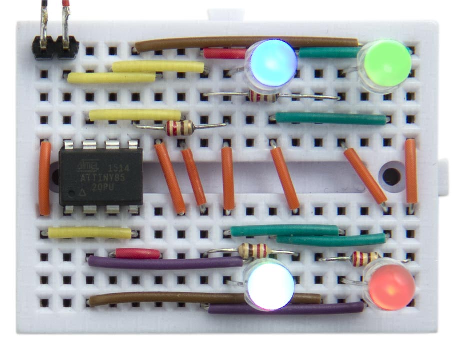
Driving four RGB LED packages from an ATtiny85.
Each LED can be set to one of 16 different levels, from off to full brightness, and the circuit leaves one I/O pin free for another application.
The circuit
Here's the circuit:
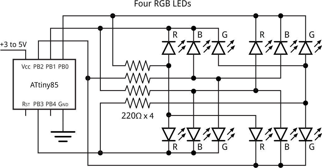
Circuit for driving four RGB LED packages from an ATtiny85.
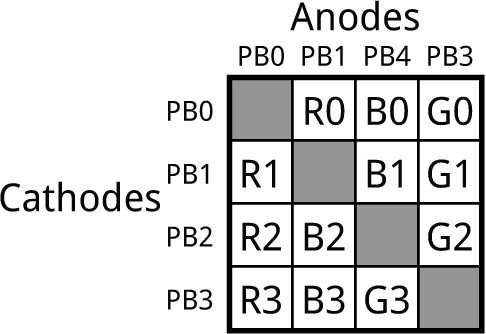
The application takes advantage of the fact that you can drive 12 LEDs from four I/O lines using charlieplexing. The following table shows which LED lights up in each RGB package when you take one I/O line high and the other I/O line low:
It's compatible with common-cathode RGB LED packages; I used low-cost four-lead common-cathode 5mm RGB LEDs [1], but you should be able to use any sort of RGB LEDs.
Display multiplexing
The LEDs are updated in the background, from the values in Buffer[], using interrupts generated by Timer/Counter1, leaving Timer/Counter0 free for use by delay() and millis().
Each element of the array Buffer[] determines the colour and brightness of one RGB LED. The value is specified as three hexadecimal digits, for the colours BGR. A value of 0 specifies zero brightness, and a value of 'F' specifies full brightness. For example:
Buffer[0] = 0xF00; Buffer[1] = 0x0F0; Buffer[2] = 0x00F; Buffer[3] = 0x888;
sets the four LEDs to 100% green, 100% blue, 100% red, and 50% white respectively.
The timer is set up in the routine DisplaySetup() for CTC mode, counting up to OCR1C:
void DisplaySetup () {
  // Set up Timer/Counter1 to multiplex the display
  TCCR1 = 1<<CTC1 | 7<<CS10;    // CTC mode; divide by 64
  OCR1C = 24;                   // Divide by 25 -> 5kHz
  TIMSK = TIMSK | 1<<OCIE1A;    // Enable overflow interrupt
}
The Timer/Counter1 Compare A interrupt displays the next row of LEDs:
ISR(TIM1_COMPA_vect) {
  DisplayNextRow();
}
For each RGB LED package the routine DisplayNextRow() is called 16 times. The brightness value of the R, G, and B components for the specified LED package are read from the value in Buffer[led], and these then determine how many of the 16 cycles the colour will be lit for:
void DisplayNextRow() {
  static int cycle = 0;
  DDRB = DDRB & ~(1<<(cycle & 0x03));
  cycle = (cycle + 1) & 0x3F;   // 64 cycles
  int led = cycle & 0x03;
  int count = cycle>>2;
  int rgb = Buffer[led];
  int r = rgb & 0x0F;
  int b = rgb>>4 & 0x0F;
  int g = rgb>>8 & 0x0F;
  int bits = (count < r) | (count < b)<<1 | (count < g)<<2;
  bits = bits + (bits & 0x07<<led);
  DDRB = (DDRB & 0xF0) | bits;
  PORTB = (PORTB & 0xF0) | bits;
  DDRB = DDRB | 1<<led;
}
The interrupt occurs at a rate of 5kHz, so a complete set of 64 cycles of DisplayNextRow() occurs at approximately 78Hz, fast enough to avoid flicker.
Demonstration program
The following demonstration program in loop() slowly cycles the LEDs through all possible colours and brightnesses:
int Step = 0;

int red (int x) {
  int y = x % 48;
  if (y > 15) y = 31 - y;
  return max(y, 0);
}

int green (int x) { return red(x + 32); }
int blue (int x) { return red(x + 64); }

void loop () {
  for (int i=0; i<4; i++) {
    Buffer[i] = green(Step + i*12)<<8 | blue(Step + i*12)<<4 | red(Step + i*12);
  }
  Step++;
  delay(200);
}
Compiling the program
Compile the program using the ATTiny Core, which supports all the ATtiny processors and supersedes the various earlier ATtiny cores [2]. Choose the ATtiny25/45/85 option under the ATtinyCore heading on the Board menu. Then choose Timer 1 Clock: CPU, B.O.D. Disabled, ATtiny85, 8 MHz (internal) from the subsequent menus. Choose Burn Bootloader to set the fuses appropriately. Then upload the program to the ATtiny85.
Here's the whole Four RGB LED program: Four RGB LED Program.
- ^ Kingbright RGB Through Hole 5mm LEDs on Farnell.
- ^ ATTinyCore on GitHub.
blog comments powered by Disqus