Twinkling Pendant
23rd February 2022
This project is a star-shaped pendant with six coloured LEDs that twinkle in a random pattern:
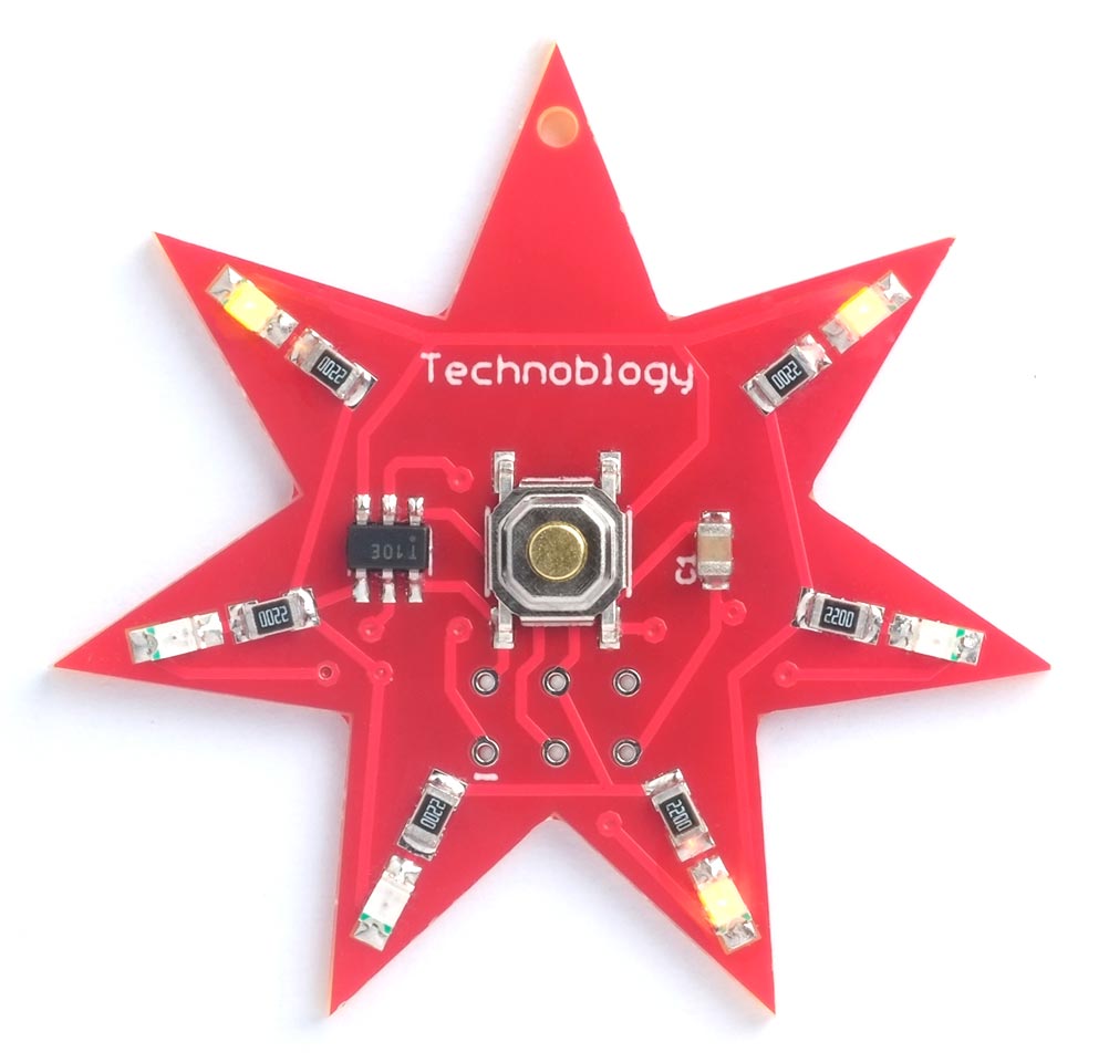
Twinkling Pendant based on an ATtiny10.
The pendant is based on the ATtiny10, a tiny AVR microcontroller in a 6-pin SOT-23 package.
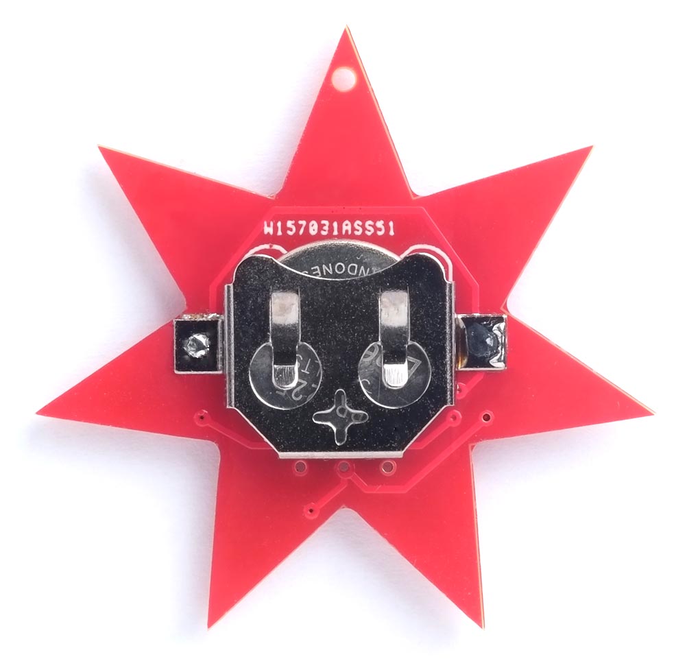
It's powered by a 3V coin cell on the back. Press the push button to start the pendant twinkling, and press it again to turn it off. Alternatively, the pendant turns off automatically after about an hour to avoid accidentally running down the coin cell.
Introduction
While designing the Morse Code Message Pendant I had the idea of making another ATtiny10-based pendant with six coloured LEDs. The ATtiny10 has three I/O pins, just enough to drive six LEDs using charlieplexing, in which every pair of lines drives two LEDs, one with each polarity.
The following diagram shows how the LEDs are connected:
For example, taking PB0 high and PB1 low lights up LED1, where LED1 is the first LED counting clockwise from the top of the pendant.
To make the LEDs twinkle I made each LED flash at a regular rate, but the rates of all six LEDs are slightly different, producing a pattern that's more interesting than simply making each LED flash randomly.
The push button is connected to the reset pin, and this turns the light display on or off. The ATtiny10 stays in sleep mode when the display is off, and the current consumption in sleep mode is under 0.1µA, giving negligible drain on the coin cell when the pendant isn't being used.
The circuit
Here's the circuit of the Twinkling Pendant:
Circuit of the Twinkling Pendant, based on an ATtiny10.
I used an ATtiny10 in an SOT-23 package. They seem to be sold out in all the suppliers in the UK or USA at the moment, but I ordered some from AliExpress; see the Parts list. The LEDs, resistors, and capacitor are all 0805 size. The LEDs can be any colour, but red, yellow, or orange will give the longest battery life because they have a lower forward voltage of 2.2V or less. I chose a mixture of red, yellow, and orange.
The button is the same as I've used on several of my projects, a miniature SMD push button available from Sparkfun [1], or Proto-PIC in the UK [2].
The pendant is designed to work with a 3V 12mm coin cell type CR1225; you could also use types CR1216 or CR1220. The coin cell fits in an SMD 12mm coin cell holder [3].
A note about the current-limiting resistors
Charlieplexing lets you control n*(n-1) LEDs using n I/O lines. You need to include current-limiting resistors to control the current through each LED. You can include one resistor in series with each I/O line, as I did with my Tiny Time Watch circuit, or you can include one resistor in series with each LED, as I've done here. What's the difference?
Having one resistor per I/O line saves resistors, but only works well if the LEDs are the same, or have the same forward voltage. Otherwise if two LEDs of different forward voltages are lit up at the same time, the one with the higher forward voltage will be dimmer.
The advantage of having one resistor per LED is that the LEDs will be equal brightness, irrespective of their forward voltages, and incidentally it fits in nicely with the design of this PCB, but a different problem arises. If you run the circuit from a supply that is more than double the LED forward voltage, such as 5V, three LEDs will light up when you only program one to light up. For example, suppose you take PB0 low and PB1 high to light up LED 3. LEDs 4 and 5 will also light up because they are effectively in series across PB0 and PB1. This isn't a problem in this circuit, as it's designed for use with a 3V cell, but it might confuse you if you're testing with a 5V supply.
► Parts list
Construction
I designed a star-shaped board in Eagle and sent it to PCBWay for fabrication. I was impressed with how well they turned out, with very clean smooth edges.
It should be possible to solder all the components by hand, using a fine-tipped soldering iron, but I used a Youyue 858D+ hot air gun set to 250°C. Once all the SMD components were soldered on the front of the board I finally soldered the coin cell holder onto the back of the board using a conventional soldering iron:
As in my recent project Morse Code Message Pendant I've brought the programming connections to a standard 2x3 pin pad so you can connect to it with a set of six pogo pins. I'll give details of how to make a suitable Pogo probe below.
The program
Timer interrupt
The program uses the ATtiny10's 16-bit Timer/Counter to generate an interrupt which is used to multiplex the LEDs. The Timer/Counter is configured in setup():
  TCCR0A = 0<<WGM00;                      // No outputs, CTC mode, top=OCR0A
  TCCR0B = 1<<WGM02 | 2<<CS00;            // Divide clock by 8
  OCR0A = 624;                            // Gives 200Hz interrupt
  TIMSK0 = 1<<OCIE0A;                     // Enable compare interrupt
The 1MHz system clock is divided by 8, so the interrupt frequency is 1000000/8/625 which is about 200Hz, which is fast enough to avoid flicker when switching between the three pairs of LEDs.
Controlling the LEDs
The variable Lights controls which LEDs are illuminated; each bit corresponds to one LED, as follows:
// LEDs:                426 153
const uint8_t Mask = 0b011101110;          // Valid light positions
The gaps in the bit pattern make the programming easier.
For example, to set LEDs 1, 3, and 6 on set Lights to:
Lights = 0b000101010
The LEDs are multiplexed by the Compare interrupt service routine:
ISR(TIM0_COMPA_vect) {
  static uint8_t Count;
  PORTB = 0;                              // All bits low
  DDRB = 0;                               // All pins inputs
  Count = (Count + 1) % 3;
  uint8_t bits = Lights>>(3*Count) & 0b111;
  DDRB = 1<<Count | bits;                 // Make outputs
  PORTB = bits;                           // Take bits high
  Ticks++;
}
Normally the three I/O lines are programmed as inputs, so none of the LEDs are turned on. During successive cycles of the interrupt service routine Count takes the values 0, 1, and 2. During one cycle the PORTB bit corresponding to Count is taken low, and the bits corresponding to the appropriate set of three bits in Lights are taken high.
The interrupt service routine also increments the global variable Ticks on each cycle. This is used to provide a simple delay routine:
void delay (uint8_t msec5) {
  Ticks = 0;
  while (Ticks < msec5);
}
The delay is in units of 5 milliseconds.
Test program
To test that all the LEDs are connected correctly you can replace loop() in the source with the following test program that simply lights each LED in turn, with a one second delay, going clockwise around the star:
void loop () {
  for(;;) {
    Lights = 0b1000; // 1
    delay(200);
    Lights = 0b1000000; // 2
    delay(200);
    Lights = 0b10; // 3
    delay(200);
    Lights = 0b10000000; // 4
    delay(200);
    Lights = 0b100; // 5
    delay(200);
    Lights = 0b100000; // 6
    delay(200);
  }
}
You will need to test the circuit with a 3V supply, because with a 5V supply multiple LEDs light at a time due to the way they are wired for charlieplexing; see A note about the current-limiting resistors above.
On/off button
The push button resets the ATtiny10, and each time the program runs it toggles the state of the variable Power:
Power = ~Power & 1;
Power is defined as .noinit, which means that it doesn't get initialised to zero when the program runs:
uint8_t Power __attribute__ ((section (".noinit")));
So it allows the push button to act as an on/off switch for the circuit.
Flash sequence
If Power is true the flashing sequence is generated by the main program in loop():
  if (Power) {
    for (int n=0; n<=32767; n++) {
      for (int i=1; i<8; i++) {
        int k = n % (30 + i);
        if (k == 0 && i != 4) Lights = Lights | 1<<i;
        else Lights = Lights & ~(1<<i);
      }
    delay(20);                            // 100 msec
    }
  }
The twinkling effect works as follows:
The circuit counts an integer n up from 1 to 32767 ten times a second. The lights are assigned the numbers 30, 31, 32, 33, 34, and 35. When n is exactly divisible by a light's number the light is illuminated; otherwise it is off. So the first light flashes at a rate of 10/30Hz, or once every three seconds. Likewise, the second light flashes at 10/31Hz, and so on up to 10/35Hz for the last light.
The result is that each light flashes at a regular rate, but because the numbers 30, 31, 32, 33, 34, and 35 are coprime, two lights are guaranteed never to flash in synchrony, and the pattern will always be changing. It will take 32767/10 seconds or 54 minutes until the pattern repeats.
Programming the ATtiny10
The procedure for programming the ATtiny10 is the same as for my earlier project Morse Code Message Pendant, but I've repeated it here to save you having to refer back to that article.
Unlike the SPI protocol used to program the older AVR chips, such as the ATmega328 in the Arduino Uno, or the UPDI protocol used by the latest AVR chips, such as the AVR128DA28, the ATtiny10 uses a programming protocol called TPI (Tiny Programming Interface) which needs five wires. Fortunately Thomas Fischl's excellent USBasp programmer supports this protocol [4]; They are widely available on eBay [5].
Connecting the USBasp
Connect the USBasp to the ATtiny10 as shown in the following diagram:
Connecting the USBasp programmer to an ATtiny10.
Making a pogo-pin programmer
If you get a USBasp programmer with a 10-pin to 6-pin adapter for ISP programming you can replace the 6-pin socket with a set of six pogo pins [6] for programming the Twinkling Pendant, as follows:
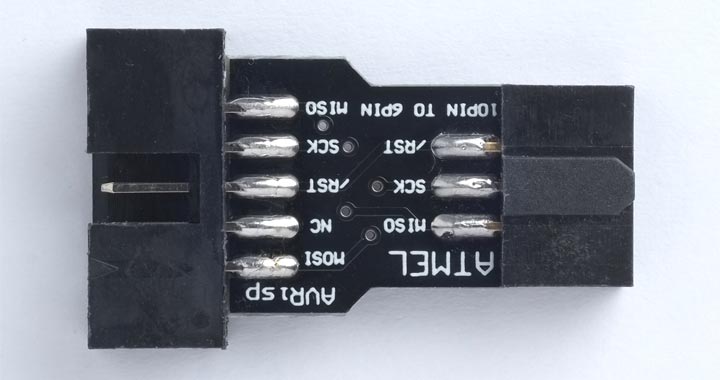
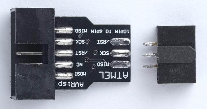
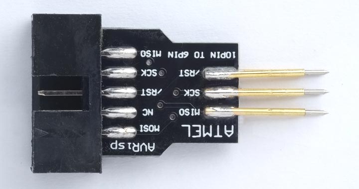
- Unplug the 10-pin to 6-pin adapter from the USBasp ribbon cable.
- Unsolder the 6-pin header socket from the adapter.
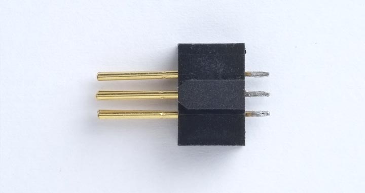
- Push the pogo pins into the header socket, point side first, to use the socket to hold the pins in the correct alignment.
- Solder the six pogo pins to the 10-pin to 6-pin adapter board, three on each side, and then remove the header socket.
You can then plug the ribbon cable back into the adapter board, and use the pogo pins to connect to the six pads on the PCB.
Uploading the program
Here are the instructions for programming the ATtiny10.
- Install the ATtiny10Core by following the instructions on my GitHub repository ATtiny10Core.
This should add an ATtiny10Core heading to the Board menu.
- Choose Board from the Tools menu, and select the ATtiny10/9/5/4 option under the ATtiny10Core heading; it's the only option.
- Choose ATtiny10 from the Chip menu.
- Choose USBasp from the Programmer option on the Tools menu.
- If you have inserted a battery in the Twinkling Pendant board, remove it before programming.
- Press the USBasp pogo pins to make contact with the six pads on the pendant PCB, aligning the GND terminal with the pad marked with a white bar.
- Choose Upload to upload the program.
Resources
Here's the Twinkling Pendant program: Twinkling Pendant Program.
Or get the program from GitHub, together with the Eagle files for the PCB so you can make yourself a board: https://github.com/technoblogy/twinkling-pendant.
Or order boards from OSH Park here: Twinkling Pendant.
Or order boards from PCBWay here: Twinkling Pendant.
- ^ Mini Push Button Switch - SMD on SparkFun.
- ^ Mini Push Button Switch (SMD) on Proto-PIC.
- ^ Coin Cell Battery Holder - 12mm (SMD) on Farnell.
- ^ USBasp - USP programmer for Atmel AVE controllers on www.fischl.de.
- ^ USBASP Programmer Cable & Adapter on eBay.
- ^ Pogo pins "Needle Head" (10 pack) on Adafruit.
blog comments powered by Disqus