Logic Lab Problem Answers
25th May 2023
In my previous post I described Logic Lab, which provides a selection of 12 logic gates that you can interconnect with patch cables to experiment with a variety of different logic circuits.
Here are the solutions to the logic problems posed in that article. Note that there are often several ways to solve each problem; in these cases I've tried to choose the simplest.
Traffic lights
The problem was to design a logic circuit that lights the red, orange, and green LEDs like UK traffic lights according to the sequence of switches S0 and S1:
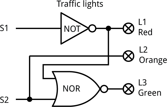
The red LED is on whenever S1 is '0', so we can connect it directly to S1 via a NOT gate.
The orange LED is on whenever S2 is '0', so we can connect it directly to S2.
The green LED is on only when S1 is '1' and S2 is '0', so we can connect it to the output of a NOR gate driven by NOT S1 and S2.
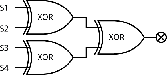
Exclusive-OR
The problem was to design an exclusive-OR gate without using the XOR gates, by using a combination of the other gates in the Logic Lab.
Here's one way of doing it:
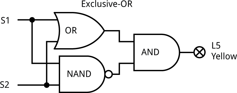
An XOR is like an OR, but with the case when both inputs are '1' excluded. This is achieved by the NAND and AND gates.
Another way to do it uses two NOR gates and an AND gate.
Safety switch
The problem was to design a logic circuit that turns on a red warning LED only if all switches are set to '1'.
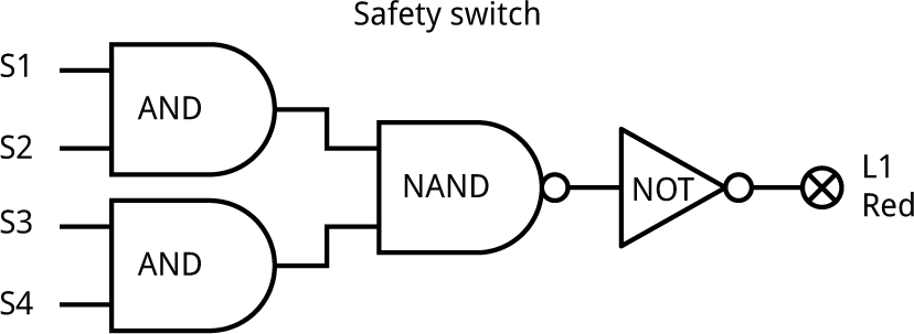
The solution would be a four-input AND gate, but we only have two two-input AND gates. We can achieve the same effect with three AND gates, creating a third AND gate from a NAND gate followed by a NOT gate.
Alternatively you could use two NAND gates and one NOR gate.
Palindrome checker
The problem was to design a circuit that lights the green LED if the four switches are set to a binary number that's a palindrome, such as '1001', and the red LED if it's not a palindrome, like '1011'.
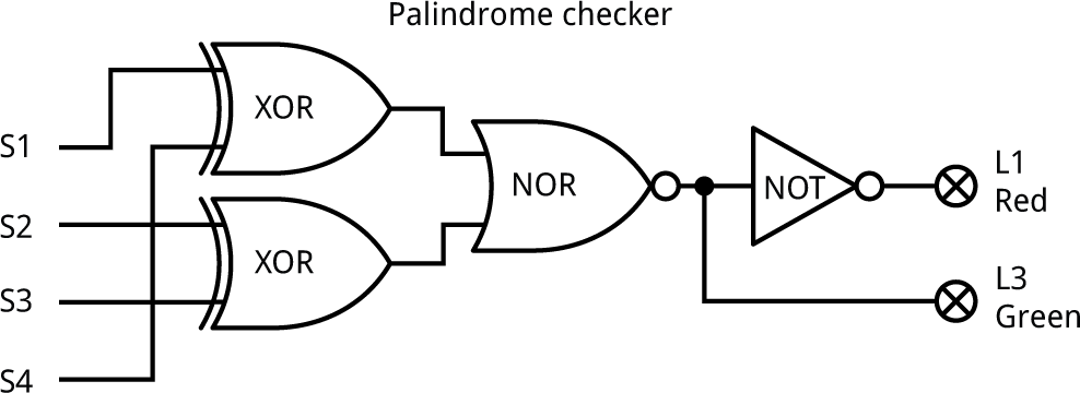
The switches form a palindrome if S1 = S4 and S2 = S3.
The output of the top XOR gate is '0' only if S1 and S4 are the same. Likewise, the output of the bottom XOR gate is '0' only if S2 and S3 are the same.
Combining these with a NOR gate gives an output on L3, the green LED, that's '1' for a palindrome. We can use a NOT gate to light L1, the red LED, if it's not a palindrome.
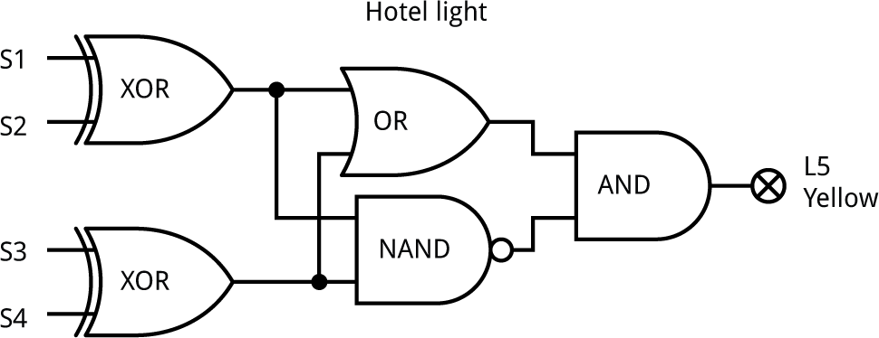
Hotel light
The problem was to design a circuit that allows each of the four switches S1 to S4 to turn the light L5 on or off.
To control a light with either of two switches you would use an XOR gate. So the solution with four switches would be to use three XOR gates:
We have only got two XOR gates in the Logic Lab. Fortunately you can construct an XOR gate from three of the other gates, as described in the Exclusive-OR problem earlier, so here's the solution:
Binary decoder
The problem was to design a circuit that lights up just one of the four LEDs L1 to L4 for each of the different possible settings of switches S1 and S2:
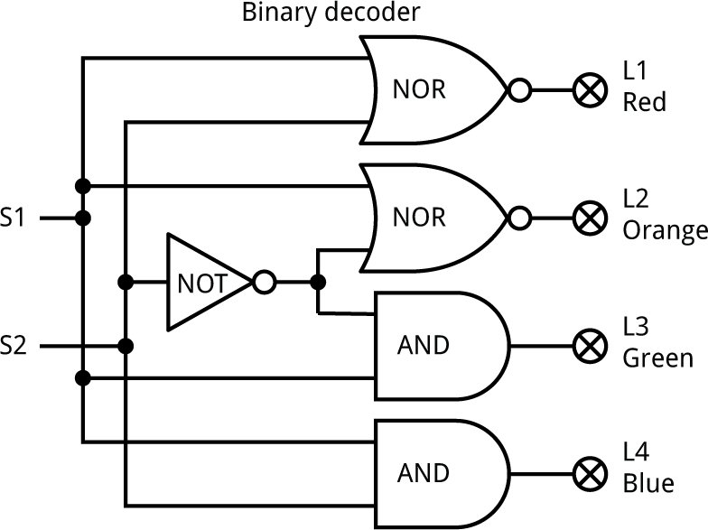
For this circuit you'll need to use the busses, J1 and J2, above and below the output LEDs.
Each LED is driven by a gate whose output should be high only for the correct values on its inputs.
Working up from the bottom, for the inputs '11' an AND gate gives the required output.
For the inputs '10" an AND gate with the second input inverted gives the required output.
For the inputs '01" the gate could be an AND gate with the first input inverted, but we've run out of AND gates. A NOR gate is equivalent to an AND gate with both inputs inverted, so we can use that.
Finally, for the inputs '00' the gate could be an AND gate with both inputs inverted. This is equivalent to a NOR gate.
Majority vote
The problem was to design a circuit that will light the green LED if the majority of switches S1 to S3 are set to '1', or the red LED if they aren't.
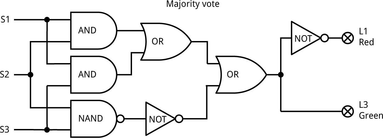
There's a majority if one (or more) of the following are true: S1 and S2 are '1', S1 and S3 are '1', or S2 and S3 are '1'. We can test those three conditions with AND gates, using a NAND gate and NOT as a third AND gate.
We then combine the three conditions with two OR gates, with the output connected to the green LED. Finally, we use a NOT gate to light the red LED when the green LED isn't on.
Combination switch
The problem was to design a circuit that lets you specify one of the 16 possible passwords, such as '1011', It should then only light up the green LED if you set the correct password on the switches.
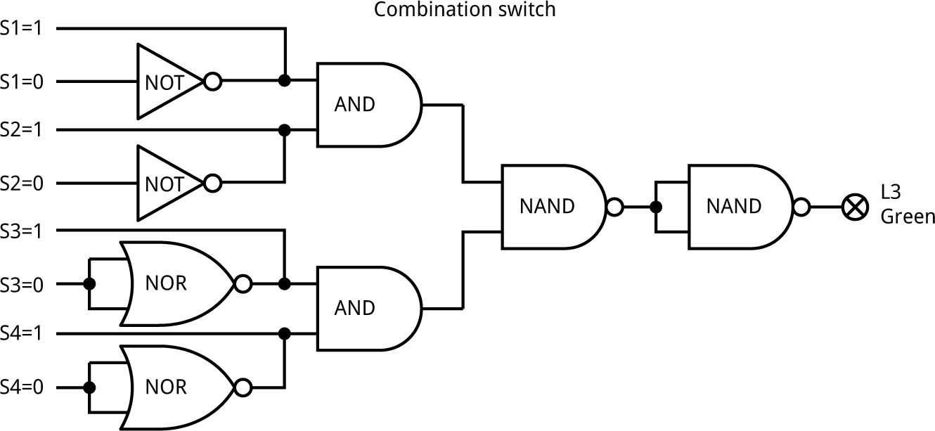
To configure the password connect S1 to 'S1=1' if the first digit of the password is '1', and to 'S1=0' if the first digit of the password is '0', and so on for the three other switches.
We connect each switch into an AND gate if that digit is a '1', or via an inverter if that digit is a '0', using two spare NOR gates as two of the inverters.
The rest of the circuit is effectively a four-input AND gate to check that the four digits are correct.
Binary adder
The problem was to design a circuit that will add together two 2-digit binary numbers, on S1,S2 and S3,S4, and put the answer in binary on the three LEDs L3 to L5.
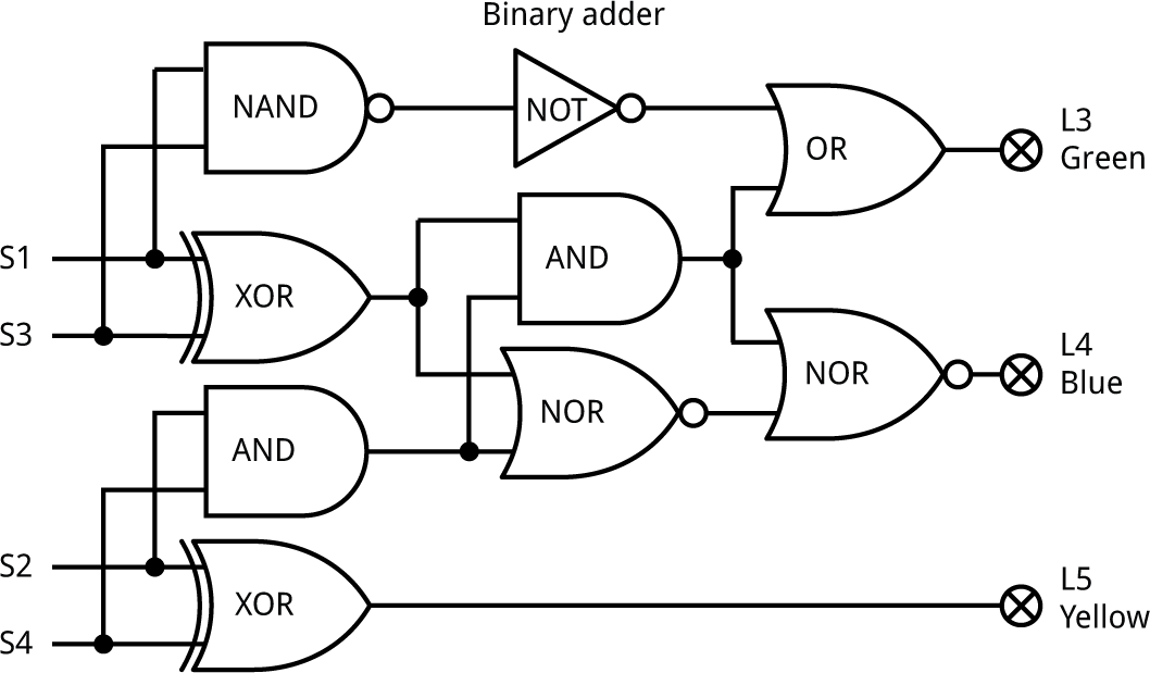
The bottom XOR gate adds the low-order bits of the two numbers, S2 and S4, and the bottom bit of the sum goes to L5. If both S2 and S4 are '1' there's a carry, detected by the AND gate above it.
Likewise, the middle XOR gate adds the high-order bits of the two numbers, S1 and S3. If they are both '1' the NAND gate and NOT gate behave like an AND gate and there's a carry to L3.
L3 is also set to '1' if there was a carry from S2 and S4, and S1 or S3 is '1'.
Finally, L4 is set to '1' only if the inputs of the NOR gate connected to it are both '0'. This can happen if just one of the following two conditions is true: there was a carry from S2 and S4, or one of S1 and S3 is '1'.
blog comments powered by Disqus