Odometer/Speedometer Pendant [Updated]
31st May 2015
This article describes an Odometer/Speedometer Pendant I built for a friend who is keen on walking, and wanted to see how far she'd walked each day. It's small enough to be hung round the neck on a lanyard, and displays the distance travelled in miles (up to 400 miles). It can also be switched to show the speed in mph, or the time in hours and minutes.

The Odometer/Speedometer Pendant is based on an ATtiny84, and uses a cheap GPS module, the Gtop010 (also known as the GTPA010 or PA6C) available from PV Electronics for under £20 in the UK [1]. Alternatively, the similar Gtop013 (or PA6H) is available from Adafruit [2]. To keep the circuit as small as possible I used a 4-digit bubble display. These used to be available from Sparkfun [3] but unfortunately they are now discontinued. You may occasionally be able to find them on eBay. I built it on one of Adafruit's Perma-Proto Small Tin prototyping boards [4]:
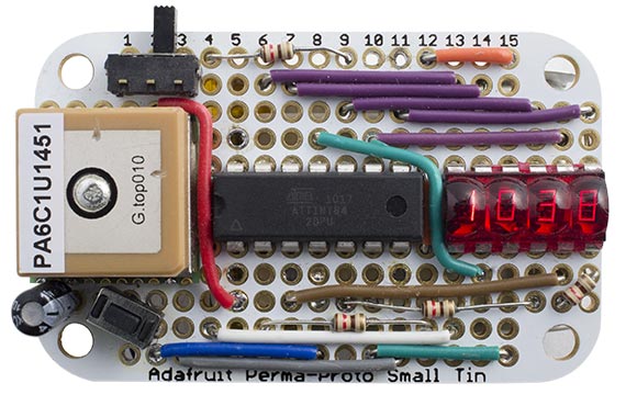
The Odometer/Speedometer Pendant, based on an ATtiny84.
Driving the display
The Odometer/Speedometer Pendant is based on my Simple GPS Odometer, but redesigned to use the more compact ATtiny84 so it would all fit on the prototyping board. The ATtiny84 provides 11 I/O lines. Pin A6 is dedicated for use by the USI input, leaving 10 lines to drive the display. There are seven segments plus decimal points, and four digits, so it looks as if we'll need 12 I/O lines. Using a couple of tricks I reduced this to the ten available:
- I restricted the leftmost display position to displaying 1, 2, or 3, none of which use segment f. We can therefore use the same pin to drive the f segments and digit 0.
- We don't need to display the rightmost decimal point, so we can use the same pin to drive the dp segments and to drive digit 4.
The display is generated under interrupt, using the contents of the array Buffer[]. For example, to display "2345" execute:
Buffer[0]=2; Buffer[1]=3; Buffer[2]=9; Buffer[3]=5;
The program uses Timer/Counter1 to generate an interrupt at 200Hz, which is used to multiplex the display. To make it easier to wire up the circuit on the breadboard I connected the segments to arbitrary pins on Port A. The array Segments[] specifies how they are wired, and the routine ReorderBits() then reorders the bits in the segment definitions to account for this:
void ReorderBits() {
  char segs, newsegs;
  for (int i=0; i<charArrayLen; i++) {
    segs = charArray[i];
    newsegs = 0;
    for (int i=0; i<8; i++) {
      newsegs = newsegs | ((segs & 1)<<Segments[i]);
      segs = segs >> 1;
    }
    charArray[i]=newsegs;
  }
}
Counter/Timer1 is then configured by InitialiseDisplay():
void InitialiseDisplay () {
  TCCR1A = 0<<WGM10;
  TCCR1B = 1<<WGM12 | 2<<CS10;  // Divide by 8
  OCR1A = 4999;                 // Compare match at 200Hz
  TIMSK1 = 1<<OCIE1A;           // Compare match interrupt enable
  TIMSK0 = 0;                   // Stop delay/millis using Timer/Counter0
}
The compare match interrupt service routine then simply calls DisplayNextDigit():
ISR (TIMER1_COMPA_vect) {
  DisplayNextDigit();
}
This reads the data in the appropriate element of Buffer[] and lights the segments in the corresponding display digit:
void DisplayNextDigit () {
  pinMode(Digits[digit], INPUT);
  digit = (digit+1) % ndigits;
  char segs = charArray[Buffer[digit]];
  // Display decimal point?
  if (digit == dp) {
    PORTB = PORTB | 1<<dpSeg;
    DDRB = DDRB | 1<<dpSeg;
  } else DDRB = DDRB & ~(1<<dpSeg);
  DDRA = 0;     // All inputs
  PORTA = segs & 0xBF; // 1 = high
  DDRA = segs & 0xBF;  // 1 = output except PA6
  pinMode(Digits[digit], OUTPUT);
  digitalWrite(Digits[digit], LOW);
}
Because PA6 is dedicated to the USI serial input we have to mask this bit out when writing to port A.
Finally, the routine Display() converts an unsigned integer to the appropriate four-digit decimal number in Buffer[], with leading-zero suppression. The odometer shows hundredths of a mile from 0.00 miles to 39.99 miles, and then switches range to display tenths of a mile from 40.0 miles upwards. The largest number that can be displayed is 399.9 miles:
void Display (unsigned int number) {
  boolean dig = false;
  int j;
  if (number>3999) { j=10000; dp=2; }
  else { j=1000; dp=1; }
  for (int d=0; d<4 ; d++) {
    int i = (number/j) % 10;
    if (!i && !dig && j>100) Buffer[d]=Space;
    else { Buffer[d]=i; dig = true; }
    j=j/10;
  }
}
Reading the GPS data
The ATtiny84 doesn't provide a USART, so I implemented a simple 9600 baud receive-only UART using the ATtiny84's USI, as described in an earlier article: Simple ATtiny USI UART 2.
The AVR internal clocks are accurate to within 10%, which is not good enough for use with a UART. I didn't have enough pins available to use a crystal, so I calibrated the internal clock using the OSCCAL register. I determined the correct value of OSCCAL by generating 1/64 of the clock frequency on I/O pin B2:
  pinMode(2, OUTPUT);            // PINB2
  TCCR0A = 1<<COM0A0 | 2<<WGM00; // Toggle OC0A (PB2)
  TCCR0B = 1<<WGM12 | 3<<CS00;   // Clock/64 giving 62.5kHz
I then measured this frequency with a frequency meter, and recompiled the program with different OSCCAL values until the meter read 62.5kHz.
When a byte has been received by the USI a USI overflow interrupt is generated, and the interrupt service routine simply calls ParseGPS() to process the received character. This is described in my earlier article Minimal GPS Parser [Updated].
Selecting the display mode
The pocket odometer has three display modes: distance, speed, and clock. I used a push button connected to the Reset pin to switch between modes. The current mode and accumulated distance are stored in the variables Mode and Distance, and these are given the following declaration to ensure that they don't get initialised on reset:
__attribute__ ((section (".noinit")));
The setup() routine calibrates the clock, and then reads the MCU Status register, MCUSR, to determine whether the reset was caused by a power-on reset or the reset button:
 if (MCUSR & 1) { Distance = 0; Mode = 0; }
 else Mode = (Mode+1) % 3;
If the bottom bit of MCUSR is set it was a power-on reset, and we clear the Distance and Mode; otherwise we step to the next of the three modes.
Finally the setup() routine initialises the USI and display multiplexing, and displays a flashing dash on the display until the GPS module gets a fix.
Main loop
The main loop reads the speed and clock, and updates the distance calculation. It then displays the distance, speed, or clock depending on the current mode:
void loop () {
  unsigned int Speed, Clock;
  // Wait for fresh data at 1Hz
  do ; while(!Fix);
  cli(); Speed = Knots; Clock = Time; sei();
  Fix = 0;
  if (Speed > Stationary) Distance = Distance + Speed;
  // Value of Mode determines what we display
  if (Mode == 0) Display(Distance*19/59438);
  else if (Mode == 1) Display((long)Speed*38/33);
  else Display(Clock);
}
The GPS module can give small speed values even when you are stationary; to avoid these accumulating to give an apparent distance reading the program ignores speed values less than 100 (1 knot).
If Mode is 0 the display shows the distance in miles with two decimal places. To calculate this the speed in knots, accumulated every second, is multiplied by 1.151 and divided by 3600; 19/59438 gives a good rational approximation to this.
If Mode is 1 the display shows the speed in miles per hour. To calculate this the speed in knots is multiplied by 1.151; 38/33 gives a good approximation to this.
If Mode is 2 the display shows the time, in hours and minutes. Note that this is GMT; you will need to do some extra programming if you want to account for Daylight Saving Time/Summertime.
If you want to display the distance in km and the speed in km/h change these lines to:
  if (Mode == 0) Display(Distance*13/25270);
  else if (Mode == 1) Display((long)Speed*50/27);
You could also add an extra mode to display the average speed, since the start of the journey.
The circuit
Here's the circuit, drawn to roughly reflect the way the parts were connected up on the board:
The Odometer/Speedometer Pendant circuit.
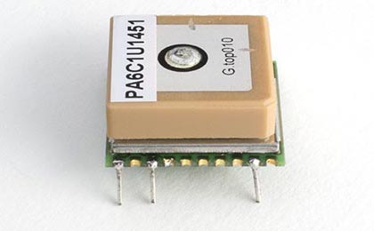
The GPS module is designed for surface mounting, but it was relatively easy to mount it on the protyping circuit board using the following procedure:
- I soldered wires from the VCC, GND, and Tx connections on the module:
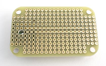
- I then aligned the wires with holes on the prototyping board.
- I enlarged the hole on the prototyping board that lined up with the antenna in the centre of the module to 3mm diameter, as recommended on the GPS module datasheet [5]:
- Finally I attached the GPS module to the board using a double-sided sticky pad, and soldered the wires to the pads on the board.
I powered the circuit from a compact 3.7V LIPO battery, attached to the back of the board with a double-sided sticky pad.
Note: The GPS module is rated at a maximum supply voltage of 4.3V, so you should disconnect it from the circuit while programming the ATtiny84 using the Tiny AVR Programmer, which supplies 5V to the circuit. Alternatively, power the GPS module via a 3.3V regulator.
Compiling the program
I compiled the program using Spence Konde's ATTiny Core, which supersedes the various earlier ATtiny cores [6]. Select the ATtiny x4 series option under the ATtiny Universal heading on the Boards menu. Then choose B.O.D. Disabled, Pin Mapping: Counterclockwise (like ATTiny Core), ATtiny84, 8 MHz (internal) from the subsequent menus. Choose Burn Bootloader to set the fuses appropriately. Then upload the program using ISP (in-system programming); I used Sparkfun's Tiny AVR Programmer Board; see ATtiny-Based Beginner's Kit.
Here's the whole Odometer/Speedometer Pendant program: Odometer/Speedometer Pendant Program.
Update
11th March 2017: I've updated the program to use the latest version of ParseGPS(), and made a few minor changes to ensure that it compiles correctly using Spence Konde's ATTiny Core.
- ^ Micro GPS Module on PV Electronics.
- ^ Ultimate GPS Module on Adafruit.
- ^ Bubble Display - 7-Segment (4-digit) on Sparkfun.
- ^ Adafruit Perma-Proto Small Mint Tin Size Breadboard PCB on Adafruit.
- ^ GTPA010 Datasheet on Adafruit.
- ^ ATTinyCore on GitHub.
blog comments powered by Disqus