I2S Speaker for QT Py
27th April 2023
This is an expansion board for QT Py microcontroller boards to provide a 3W stereo power amplifier output from the digital I2S output:
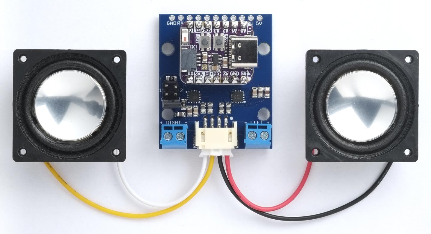
The I2S Speaker for QT Py lets you turn a QT Py ESP32 board into a stereo Bluetooth speaker,
Internet radio, or SD-Card MP3 player.
For example, it allows you to create a stereo Bluetooth speaker, Internet radio, or SD-Card MP3 player based on a QT Py ESP32 Pico board. I give examples of each of these applications below.
Introduction
I've been experimenting with using the ESP32 for I2S digital audio, and decided to design a board that would allow you to drive two loudspeakers from the I2S stream generated by one of the QT Py form-factor boards, such as Adafruit's QT Py ESP32 Pico [1]. See below for a full list.
I was inspired by the design of Adafruit's I2S 3W Stereo Speaker Bonnet for the Raspberry Pi [2], but wanted something that a QT Py board would fit on, so I decided I would have to design my own.
It's based on two MAX98357A PCM-input class D amplifiers [3], one for each channel, and will provide up to 3 watts into 4Ω to 8Ω speakers using a 5V power supply. You could also power it from a 3.7V LiPo cell, but this will give a slightly lower output.
Obviously you could use the I2S Speaker for QT Py with other boards, but you would need to connect wires between the board and the appropriate pins on the speaker board.
QT Py compatible boards
At time of writing I'm aware of the following QT Py form-factor boards that can potentially be used with this I2S Speaker board:
| Board | Wi-Fi | Bluetooth | Flash | Link |
| QT Py SAMD21 | No | No | 256Kbytes | Adafruit QT-Py SAMD21 |
| XIAO SAMD21 | No | No | No | Seeed Studio XIAO SAMD21 |
| QT Py ESP32 Pico | Yes | Classic | 8Mbytes | Adafruit QT Py ESP32 Pico |
| QT Py ESP32-S2 | Yes | No | 4Mbytes | Adafruit QT Py ESP32-S2 |
| QT Py ESP32-S3 | Yes | LE | 8Mbytes | Adafruit QT Py ESP32-S3 |
| QT Py ESP32-C3 | Yes | LE | 4Mbytes | Adafruit QT Py ESP32-C3 |
| XIAO ESP32-C3 | Yes | LE | No | Seeed Studio XIAO ESP32-C3 |
| XIAO nRF52840 | Yes | LE | No | Seeed Studio XIAO nRF52840 |
| QT Py RP2040 | No | No | No | Adafruit QT Py RP2040 |
| XIAO RP2040 | No | No | No | Seeed Studio XIAO RP2040 |
The I2S Speaker board could also be used with other form-factor boards, but you will need to connect cables between the appropriate pins on the boards.
Applications
The combination of a QT Py board with this I2S Speaker board can potentially be used for a range of digital audio applications, including:
- A Bluetooth speaker, that plays music streamed from a mobile phone, tablet, computer, or Apple Watch.
- An Internet radio, that connects to your local Wi-Fi network and plays music streamed from an Internet radio station.
- An MP3 player that can play MP3 music files from an SD Card connected to the QT Py.
Not all QT Py boards can be used for all applications:
- For the Bluetooth speaker you need a board that supports Bluetooth Classic A2DP audio. Currently the only QT Py board that does this is the QT Py ESP32 Pico.
- For the Internet radio you need a QT Py board that supports Wi-Fi.
- For the MP3 player you need a QT Py board connected to an external SD-Card socket.
The best choice if you want to experiment with these applications is the Adafruit QT Py ESP32 Pico board, which works well in all three applications.
This I2S Speaker board can also be used with the whole range of digital audio applications provided by Phil Schatzmann's excellent Arduino Audio Tools library on GitHub. For details of the features it supports see his Arduino Audio Tools Wiki.
The circuit
Here's the circuit of the I2S Speaker board:
The I2S Speaker for QT Py, based on two MAX98357A Class D amplifier ICs.
I2S connections
The QT Py boards provide 14 pins on the edge connectors. Three of them are power pins, leaving 11 general I/O pins. QT Py boards adhere to standard positions for the SPI port (3 pins), I2C port (2 pins), Serial port (2 pins), and analogue inputs A0 to A3.
I2S digital audio output requires three pins, and you can use any of the 14 general I/O pins. In this I2S Speaker board I chose to use the three pins normally used for SPI, as follows:
| Pin label | I2S function | Other names |
| MO or MOSI | LRCLK | WS |
| MI or MISO | BCLK | BCK |
| SCK | DIN | DATA_IN |
Different QT Py boards use different Arduino pin numbers for the SPI pins. For example, on the Adafruit QT Py ESP32 Pico the pin numbers are defined in the Arduino core as follows:
static const uint8_t MOSI  = 13;
static const uint8_t MISO  = 12;
static const uint8_t SCK   = 14;
The easiest way to refer to the three pins I'm using for I2S is with their standard names, MOSI, MISO, and SCK. Note that we are just doing this as an easy way to get the pin numbers used for I2S: it doesn't mean I'm using SPI for the interface.
Although this prevents you from using these pins for SPI, you can specify that you want to use any other convenient I/O pins for SPI instead; see the SD-Card MP3 Player application below for an example.
Ferrite beads
The Class D amplifier used in the MAX98357A generates a PWM square-wave output at about 300kHz. This isn't a problem for driving loudspeakers, because the inductance of the voice coil effectively filters out the high frequency. However, with speaker leads longer than about 30cm there's the possibility of electromagnetic interference with other devices. The four ferrite beads in the output lines minimise this, by acting as a high impedance to the high frequencies. You could leave them out, and replace them with 0Ω resistors, if you have short speaker leads; for example, if you're mounting the I2S Speaker in the same box as the loudspeakers.
Gain
The MAX98357A provides a GAIN pin that lets you configure the gain of the device to one of five gains, depending on whether it is connected to GND through a 100kΩ resistor (15dB), connected to GND (12dB), unconnected (9dB), connected to VDD (6dB), or connected to VDD via a 100k resistor (3dB). I wanted to provide all five options, and initially thought of using a miniature rotary selector switch, but that was very expensive, and would also take a lot of board space.
I therefore decided on two rows of header pins, using a jumper in one of five positions to select the gain. It was quite fun trying to come up with the best solution to this, with the condition that it shouldn't be possible to put the jumper in a position that would short VDD and GND! I started with 2x5 header pins, using the five possible horizontal positions of a jumper for each of the gain settings, but eventually refined it down to 2x3 header pins, with the jumper in the four possible vertical positions and one horizontal position, as marked on the PCB:
► Parts list
Construction
I designed a PCB in Eagle and sent it to PCBWay [4] for production.
The MAX98357A PCM Class D amplifiers are in TQFN-16 packages, and all the other components apart from the connectors are surface-mount 0805 devices, so it will be difficult to assemble with a soldering iron. I used a Youyue 858D+ hot air gun at 275°C and Chip Quik SMD291AX10T3 solder paste, but you could also use a reflow oven.
The loudspeakers should be between 4Ω and 8Ω, and can either be connected to the screw terminal blocks, or to the 4-way JST PH socket.
The board includes a footprint to allow you to plug in a QT Py or XIAO board. You could use standard male and female 7-way 0.1" headers, but the 7-way female headers are hard to find, and the 8-way ones are difficult to cut down neatly. They also raise the QT Py board quite a long way above the PCB. Instead I used Swiss plug [5] and socket [6] headers which are lower profile, and you can cut them into shorter lengths by sacrificing one pin, breaking at that point, and then carefully filing down the cut end:
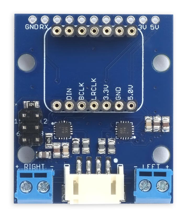
The I2S Speaker board showing the header pin sockets for the QT Py board.
The three pins normally used for the SPI interface are used for the three I2S connections to the amplifier chips, and the unused QT Py pins are brought to an 11-way header at the edge of the board so you can connect external devices. You can also connect an I2C device to the Stemma QT connector provided on many QT Py boards.
Applications
These applications all use Phil Schatzmann's Arduino Audio Tools and ESP32-A2DP libraries, which you should install from GitHub. If you're not familiar with GitHub, the easiest way is to:
- Click the <> Code button in each of the above repositories, and choose Download ZIP from the drop-down menu.
- Locate the package in your downloads location, and if necessary unzip it.
- Move it into the libraries folder in your Arduino Sketchbook folder.
They will be called arduino-audio-tools-main and ESP32-A2DP-main.
Bluetooth speaker
This application allows you to stream music to the I2S Speaker from a mobile phone, tablet, computer, or Apple Watch, using the Bluetooth Classic A2DP protocol. I've tested it with the Adafruit QT Py ESP32 Pico.
#include "AudioTools.h"
#include "BluetoothA2DPSink.h"

BluetoothA2DPSink a2dp_sink;
I2SStream i2s;

void setup() {
  auto cfg = i2s.defaultConfig(TX_MODE);
  // The I2S Speaker board uses these pin positions for I2S:
  cfg.pin_bck  = MISO;
  cfg.pin_ws   = MOSI;
  cfg.pin_data = SCK;
  i2s.begin(cfg);
  a2dp_sink.start("QT Py Speaker");
}

void loop() {
}
The I2S Speaker will appear as a device called QT Py Speaker in your Bluetooth settings.
Internet radio
This application streams music to the I2S Speaker from an Internet radio station, by connecting the QT Py board to your local Wi-Fi network:
#include "AudioTools.h"
#include "AudioCodecs/CodecMP3Helix.h"

const char *urls[] = {
  "https://stream.resonance.fm/resonance",  // Resonance FM, London
  "http://stream.srg-ssr.ch/m/rsj/mp3_128"  // Radio Swiss Jazz
};
const char *wifi = "MyWiFi";
const char *password = "MyPassword";

URLStream urlStream(wifi, password);
AudioSourceURL source(urlStream, urls, "audio/mp3");
I2SStream i2s;
MP3DecoderHelix decoder;
AudioPlayer player(source, i2s, decoder);

// #define BUTTON 0; // BOOT button; uncomment for ESP32-S2

void setup() {
  auto cfg = i2s.defaultConfig(TX_MODE);
  // The I2S Speaker board uses these pin positions for I2S:
  cfg.pin_bck  = MISO;
  cfg.pin_ws   = MOSI;
  cfg.pin_data = SCK;
  pinMode(BUTTON, INPUT_PULLUP);
  i2s.begin(cfg);
  player.setVolume(0.25); // 1.0 maximum
  player.begin();
}

void loop() {
  // Moves to the next url when you press BOOT
  if (digitalRead(BUTTON) == 0) {
    player.next();
    while(digitalRead(BUTTON) == 0);
  }
  player.copy();
}
It provides a list of Internet radio URLs, and lets you step between URLs by pressing the BOOT button on the QT Py ESP32 Pico. I've tested it on the Adafruit QT Py ESP32 Pico, Adafruit QT Py ESP32-S2, and Adafruit QT Py ESP32-C3.
This example is based on the example player-url-i2s in the Arduino Audio Tools examples. See that example for details of how to send debugging information to the Serial Monitor, or provide a volume control on an analogue input pin.
SD Card MP3 player
This application plays MP3 music files from an SD Card in an SD Card socket connected to the QT Py. The SD-Card socket will need four SPI connections, plus GND and 3.3V. There is no need for a regulator or logic-level conversion because SD Cards are happy with 3.3V levels.
The following example assumes you have connected the SD-Card socket like this:
| SD-Card Pin | QT Py Pin |
| MOSI | A3 |
| MISO | SDA |
| SCK | SCL |
| SS | TX |
| 3.3V | 3V |
| GND | GND |
Again, we're just using the labels A3, SDA, etc as a convenient way of mapping to the correct Arduino I/O pin numbers; we're not connecting to the SD-Card via I2C!
#include "AudioTools.h"
#include "AudioLibs/AudioSourceSD.h"
#include "AudioCodecs/CodecMP3Helix.h"

const char *startFilePath="/";
const char* ext="mp3";
AudioSourceSD source(startFilePath, ext, TX); // SS
I2SStream i2s;
MP3DecoderHelix decoder;
AudioPlayer player(source, i2s, decoder);

void setup() {
  // Move the SPI port to these pins:
  SPI.begin(SCL, SDA, A3, TX); // CLK, MISO, MOSI, SS

  auto cfg = i2s.defaultConfig(TX_MODE);
  // The I2S Speaker board uses these pin positions for I2S:
  cfg.pin_bck  = MISO;
  cfg.pin_ws   = MOSI;
  cfg.pin_data = SCK;
  i2s.begin(cfg);
  player.setVolume(0.25);
  player.setAutoNext(true);
  player.begin();
}

void loop() {
  player.copy();
}
The call:
SPI.begin(SCL, SDA, A3, TX)
reinitialises the SPI interface on different pins, since the default SPI pins are already in use for the I2S interface. Note that you also need to specify the select pin to the call to AudioSourceSD.
I've tested this application on the Adafruit QT Py ESP32 Pico, Adafruit QT Py ESP32-S2, and Adafruit QT Py ESP32-C3.
This example is based on the example player-sd-i2s in the Arduino Audio Tools examples. See that example for details of how to send debugging information to the Serial Monitor, provide a volume control on an analogue input pin, or display metadata such as the track name to the Serial Monitor. With a bit of extra programming you could display track information on an external I2C display connected to the STEMMA QT socket.
Resources
Get the examples and Eagle files for the PCB here: https://github.com/technoblogy/i2s-speaker.
Or order boards from OSH Park here: I2S Speaker for QT Py.
Or order boards from PCBWay here: I2S Speaker for QT Py.
- ^ QT Py ESP32 Pico on Adafruit.
- ^ I2S 3W Stereo Speaker Bonnet for Raspberry Pi on Adafruit.
- ^ MAX98357A datasheet on Analog.com.
- ^ PCBWay PCB prototype service.
- ^ 36-pin Swiss male plug headers on Adafruit.
- ^ 36-pin Swiss female socket headers on Adafruit.
blog comments powered by Disqus