Illuminated Button Matrix
9th May 2019
This article describes a 4 x 4 matrix of illuminated pushbuttons with a two-wire I2C interface, controlled by an ATtiny88, that you can use for games, music, or control applications:
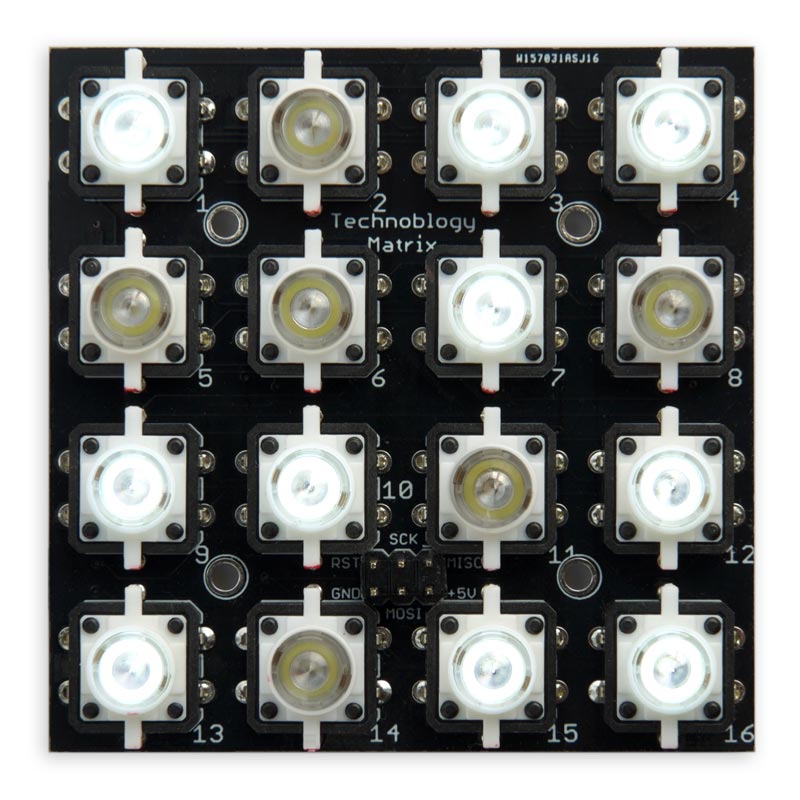
Illuminated Button Matrix with an I2C interface, based on an ATtiny88.
You can independently set the state of the lights, or read the buttons, via I2C. I've included a demo program for the Arduino Uno that uses the Button Matrix to play a puzzle game called Tacoyaki.
Introduction
I've been wanting to build an illuminated button matrix for some time, as an interface for games and music, but ruled it out as being too expensive. However, I revived the idea when I saw illuminated pushbuttons available cheaply on AliExpress [1]. The buttons are available in a variety of colours; I chose white. My final 4 x 4 Illuminated Button Matrix costs under £10/$10, excluding the PCB.
I wanted the button matrix to be free from ghosting; in other words, you should be able to press any combination of keys and read their state unambiguously. Also, pressing the buttons shouldn't affect the display of the LEDs. This is especially important for music applications; for example, so you can play chords.
Originally I tried designing it using the HT16K33, which is the approach used by Adafruit in their Trellis product [2]. However, it's not really a good fit to a 4 x 4 matrix; it requires diodes to get it to work without ghosting, and reading and writing the state via I2C is messy. I finally realised that the control could be achieved very simply using a low-cost AVR processor.
I chose the ATtiny88 which is ideal for this application because it has exactly the right number of I/O lines, and includes hardware I2C support. It lets you read the 16 buttons with no ghosting, and without needing any diodes.
The circuit
Here's the circuit of the Illuminated Button Matrix:
Circuit of the Illuminated Button Matrix.
The buttons are connected to individual I/O pins on ports B and D, so a keypress can be detected by a pin-change interrupt, and their state can be read simply by reading both ports, even when multiple keys are pressed simultaneously.
The LEDs are arranged in a 4 x 4 matrix using PC0 to PC3 for the anodes, and PA0 to PA3 for the cathodes, and multiplexing illuminates one row of LEDs at a time. The LED current-limiting resistors are in series with the columns to ensure that the brightness of the LEDs is constant irrespective of how many LEDs are illuminated on a single row.
The decoupling capacitor and pullup resistor on the Reset line improve the noise immunity of the reset signal; without them I found the circuit could get reset if you touched the reset line.
The power supply can be +5V or +3.3V, so the Button Matrix will work with 5V boards, such as the Arduino Uno, or 3.3V boards, such as the Arduino Zero.
► Parts list
The PCB
I designed the PCB in Eagle, and tried to keep the design systematic by having vertical tracks on one side of the board and horizontal tracks on the other, but it turned out to be one of the trickiest layouts I've done. I ordered boards from PCBWay; there's a link at the end of the article if you want to order one.
The ATtiny88 is in an MLF32 package, which is 5mm square and allowed me to fit the whole matrix on a PCB 66mm square. It's a bit tricky to solder because the leads are under the device, and I wouldn't recommend trying to solder it with a soldering iron. I used a hot air gun, which worked fine.
Alternatively you could adapt the board for a processor in the more usual TQFP package, but you'd need to increase the spacing between the buttons slightly. You could also use a PDIP package and put the processor outside the matrix area.
The only other components are the current-limiting resistors for the LEDs, a couple of 0.1µF decoupling capacitors, and the decoupling capacitor and pullup resistor on the Reset line, all of which were in 0805 SMD packages.
The I2C connections SDA, SCL, INT, GND, and VCC are brought to connectors on each edge of the board, so you can tile multiple boards and interconnect their edge connections. The INT pin gives a low pulse when the state of any key changes, so you can cause an interrupt on an external processor to trigger reading of the key state:
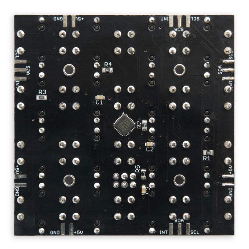
The back of the Illuminated Button Matrix circuit board.
The ISP connections are brought to an ISP connector which you can use to program the ATtiny88. I soldered a header in this position while testing the board, but subsequently removed it as it gets in the way of the buttons. Alternatively you could use Sparkfun's ISP Pogo Adapter [3] to program the board without needing to fit a header.
Assembly
I learnt from bitter experience that the pushbuttons are very tricky to unsolder, so take care when fitting them. Solder one pin and then check they are seated correctly, so you can adjust them if necessary. Because of the LED, the pushbuttons must be fitted in the correct orientation. The red blob of paint indicates the cathode, or -ve side of the LED (not the anode, as you might expect from the red colour).
I recommend the following cautious assembly procedure:
- Mount the ATtiny88, and the eight SMD resistors and capacitors.
- Use a continuity tester, such as my Continuity Tester, to check for solder bridges between adjacent pins on the ATtiny88.
- Fit one illuminated pushbutton in position 1, but initially only solder the leads to the LED.
- Fit the 3x2 pin header to the ISP connector to allow you to upload a program to the ATtiny88.
- Upload the following test program to the ATtiny88 which flashes the LEDs on all the buttons:
void setup (void) {
  // Make PC0-PC3 and PA0-PA3 outputs
  DDRC = 0x0F;
  DDRA = 0x0F;
}

void loop() {
  // Flash LEDs on all buttons
  delay(1000);
  PORTC = 0x0F;
  delay(1000);
  PORTC = 0x00;
}
- Fit the remaining buttons, periodically using this program to check them.
Using the Button Matrix
By default, the I2C address of the button matrix is 0x3A, but you can change this in the program. If you are tiling multiple boards you need to give each board a different I2C address.
Here are some examples showing how you would program the matrix lights and read the keys:
Writing to the lights
To set the state of the 16 lights you send two bytes by I2C, low order byte first. Button 1 corresponds to bit 0, and so on up to button 16 to bit 15. So to light the rightmost column of buttons, buttons 4, 8, 12, and 16, you would use the following program on the controller:
int Lights = 0b1000100010001000;
Wire.beginTransmission(0x3a);
Wire.write(Lights & 0xFF);
Wire.write(Lights>>8 & 0xFF);
Wire.endTransmission();
Reading the keys
To read the state of the 16 buttons you read two bytes by I2C. The first byte read is the low-order byte. Button 1 corresponds to bit 0, and button 16 to bit 15. For example:
  Wire.requestFrom(I2CAddress, 2);
  uint8_t Low = Wire.read();
  uint8_t High = Wire.read();
  int Keys = High<<8 | Low;
Because the bit mapping between the lights and the keys is the same, you can do:
Lights = Keys;
to set the lights to reflect the state of the buttons.
Using the interrupt output
Although you can read the Button Matrix simply by periodically polling to check the state of the keys, you can alternatively read them under interrupt using the INT interrupt output. This is pulled low when there is any change in the state of the keypad; in other words, if any key is either pressed or released.
The INT output works as an open-drain output. In its normal state it's programmed as an input with a pullup resistor, but when its active it's defined as an output and pulled low. This allows you to connect together the INT lines from multiple Button Matrixes; a keypress on any one will take the INT line low, and you can then read each Button Matrix via I2C to get the state of its keys.
The program
Setting up the LEDs
The pushbutton LEDs are arranged in a 4x4 matrix, and are multiplexed so one row is illuminated at a time. I used Timer/Counter1 to multiplex the LEDs, leaving Timer/Counter0 free for the Arduino functions millis() and delay().
First Timer/Counter1 is configured by SetupLights() to generate an interrupt at 250Hz:
void SetupLights () {
  // Set up Timer/Counter1 to multiplex the display
  TCCR1A = 0<<WGM10;            // CTC mode
  TCCR1B = 1<<WGM12 | 2<<CS10;  // CTC mode; divide by 8 = 62500Hz
  OCR1A = 249;                  // Divide by 250 -> 250Hz
  TIMSK1 = TIMSK1 | 1<<OCIE1A;  // Enable compare match interrupt
  // Make LED rows and columns outputs
  DDRC = DDRC | 0x0F;
  DDRA = DDRA | 0x0F;
}
This routine also defines the LED rows and colums as outputs.
Illuminating the LEDs
Each call to the interrupt service routine simply calls DisplayNextRow():
ISR(TIMER1_COMPA_vect) {
  DisplayNextRow();
}
This reads the appropriate set of four bits in the global variable Lights and uses them to light the LEDs in the current row:
void DisplayNextRow() {
  PORTC = PORTC & ~(0x0F);      // Take rows low
  Row = (Row+1) & 0x03;
  uint8_t Bits = Lights>>(Row*4) & 0x0F;
  PORTA = ~Bits;
  PORTC = PORTC | 1<<Row;       // Take row bit high
}
Setting up the buttons
The buttons are set up by SetupKeys() to be inputs with pullups, and pin-change interrupts are set on all these inputs:
void SetupKeys () {
  // Set up pin change interrupts on the keys
  DDRB = 0; PORTB = 0xFF;       // Port B all input pullups
  DDRD = 0; PORTD = 0xFF;       // Port D all input pullups
  PCMSK0 = 0xFF; PCMSK2 = 0xFF; // Enable PB0 to PB7 and PD0 to PD7
  PCIFR = 1<<PCIF2 | 1<<PCIF0;  // Clear interrupt flags
  PCICR = 1<<PCIE2 | 1<<PCIE0;  // Enable interrupts
  // Set up INT pin PC7 as INPUT_PULLUP
  IntRelease();
}
Initially the interrupts are cleared, and the INT pin is taken high by calling IntRelease().
The pin-change interrupt service routines simply call IntLow() to take the INT pin low:
ISR(PCINT0_vect) {
  IntLow();
}

ISR(PCINT2_vect) {
  IntLow();
}
Reading the buttons
The buttons are read by a call to ReadKeys(). This waits until the state of the buttons is stable, to eliminate contact bounce, and then returns the state of each button as a bit in the variable Keys:
int ReadKeys () {
  int Count = 0, Keys, LastKeys = -1;
  // Wait until keys are stable
  do {
    Keys = ~(PINB<<8 | PIND);
    Count++;
    if (LastKeys != Keys) Count = 0;
    LastKeys = Keys;
  } while (Count < 7);
  return Keys;
}
The I2C interface
The ATTinyCore for the ATtiny88 provides full Slave hardware I2C support, using the ATtiny88's Two-Wire Interface (TWI).
To initialise the I2C you call Wire.begin(), and then specify the routines to be called when bytes are received from the Master, or requested by the Master:
  Wire.begin(I2CAddress);
  Wire.onReceive(SetLights);
  Wire.onRequest(GetKeys);
The SetLights() routine simply reads two bytes from I2C and sets the global variable Lights accordingly:
void SetLights (int nBytes) {
  (void) nBytes;
  uint8_t Low = Wire.read();
  uint8_t High = Wire.read();
  Lights = High<<8 | Low;
}
The GetKeys() routine calls ReadKeys() to read the buttons, and then writes the value as two bytes via I2C:
void GetKeys () {
  int SendData = ReadKeys();
  Wire.write(SendData & 0xFF);
  Wire.write(SendData>>8 & 0xFF);
  IntRelease();
}
Compiling the program
I compiled the Button Matrix program using Spence Konde's ATTiny Core [4]. Choose the ATtiny48/88 option under the ATTinyCore heading on the Board menu. Then check that the subsequent options are set as follows (ignore any other options):
Chip: "ATtiny88"
Clock: "8 MHz (internal)"
B.O.D: "B.O.D. Disabled"
To program the ATtiny88 I used a USBasp programmer from eBay [5] connected to the ISP header on the board; in this case set Programmer to USBasp. Choose Burn Bootloader to set the fuses appropriately, then choose Upload to upload the program.
Here's the whole Illuminated Button Matrix program: Illuminated Button Matrix Program.
Or get the source from GitHub, together with the Eagle files for the PCB so you can make yourself a board, at: https://github.com/technoblogy/illuminated-button-matrix.
Or order a board from OSH Park here: Illuminated Button Matrix Board.
Or order a board from PCBWay here: Illuminated Button Matrix Board.
Example program
To demonstrate the Illuminated Button Matrix I've provided two simple puzzle games called Tacoyaki+ and Tacoyaki.
The games can be run on any board with I2C, such as the Arduino Uno. To run the games connect the +5V, GND, SCL, and SDA pins on any edge of the Button Matrix to the corresponding pins on the Arduino Uno:
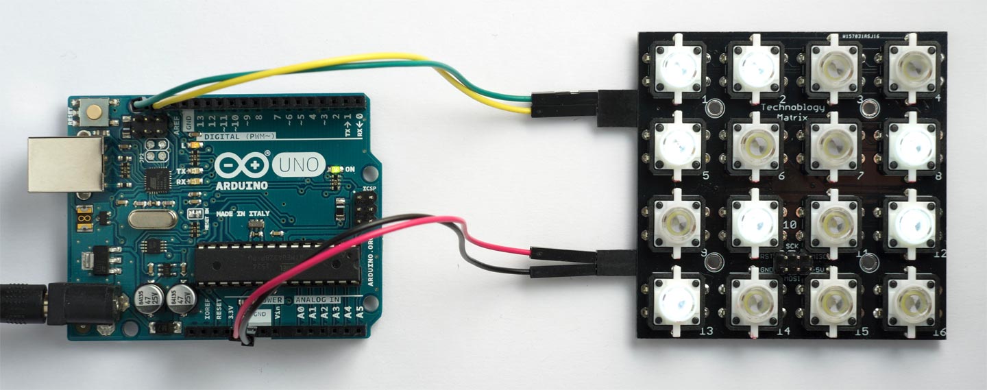
Controlling the Illuminated Button Matrix from an Arduino Uno via I2C.
Tacoyaki+
Tacoyaki+ is based on a Japanese Flash game [6]. Initially a random arrangement of lights is lit up. Pressing a button changes that light, and the vertically and horizontally adjacent lights. The aim is to get all the lights off.
When you succeed in solving the game the whole matrix of lights flashes, and then after a short delay a new random puzzle is displayed.
Tacoyaki
This is a harder puzzle game called Tacoyaki [7]. In this one pressing a button changes that light, and all the lights on the same diagonals. As before, the aim is to get all the lights off.
To run this game comment out the line:
#define Game ToyakiPlus
and remove the comment from:
#define Game Toyaki
Here's the game example program: Illuminated Button Matrix Demo.
- ^ Illuminated Tact Switch Button Switch on AliExpress.
- ^ Adafruit Trellis Monochrome Driver PCB for 4x4 Keypad & 3mm LEDs on Adafruit.
- ^ ISP Pogo Adapter on SparkFun.
- ^ ATTinyCore on GitHub.
- ^ USBASP ISP Programmer Cable Adapter from Boos Bits on eBay.
- ^ Tacoyaki+ on Gamedesign.jp.
- ^ Tacoyaki on Gamedesign.jp.
blog comments powered by Disqus