Simple Compass Display
4th December 2014
For a simple GPS navigator project I'm working on, which I hope to describe in a future article, I wanted to create a minimal compass display capable of showing the eight directions N, NE, E, SE, S, SW, W, and NW, as well as all off (for when there's no GPS fix). I hoped to do it with four LEDs for N, S, E, and W, lighting two together for the intermediate directions. Here's the finished compass display:
Simple compass display, using two I/O pins.
Obviously it's a simple matter to achieve this with four I/O pins, with one LED connected to each line. It's also possible with three I/O pins; using Charlieplexing allows you to control up to six LEDs. However, I needed to be able to do it with only two I/O lines. On the AVR micros each I/O pin has three possible states: high, low, and input (high-impedance), so in theory with two I/O pins there are 3 x 3 = 9 states, so it should be possible to achieve what I want.
The solution
The solution relies on the fact that if you choose an LED with a forward voltage drop of at least 3V at 20mA, the current at 2V is negligible, so the LED will be off. Blue or white LEDs typically have a forward voltage of 3.4V, so connecting two in series with 220Ω resistors will result in no current flowing, with both LEDs off, if powered from a 3.7V LIPO cell. The I/O line is connected to the midpoint of the two LEDs:
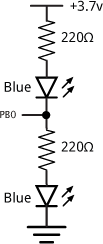
Controlling two LEDs from a single I/O pin.
Taking the I/O line high or low turns on each of the LEDs in turn; programming the I/O line as an input leaves both LEDs off. By arranging two pairs of LEDs connected like this in a square you can achieve the eight compass directions as required.
Circuit
Here's the full circuit showing how to drive two pairs of LEDs from two I/O pins of an ATtiny85:
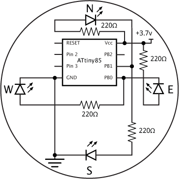
Circuit of the simple compass display.
The circuit reflects the layout I used on the prototyping board, with the LEDs arranged like the points on a compass. I used bright blue LEDs from Adafruit [1]. Note that these LEDs are very bright – I soon started getting spots in front of my eyes while testing the circuit, so increased the resistors to 1kΩ to reduce the brightness. I've also tested it with white LEDs.
Demonstration program
Here's a demonstration program that steps clockwise through the eight compass directions in turn, and then off:
void setup() {
}

void loop() {
  for (int i=0; i<8; i++) {
    pinMode(0, OUTPUT);
    if (i%4 == 0) pinMode(0, INPUT);
    else if (i/4 == 1) digitalWrite(0, HIGH);
    else digitalWrite(0, LOW);
    //
    pinMode(1, OUTPUT);
    if ((i+2)%4 == 0) pinMode(1, INPUT);
    else if ((i+2)/4 == 1) digitalWrite(1, HIGH);
    else digitalWrite(1, LOW);
    //
    delay(5000);
  }
  pinMode(0, INPUT);
  pinMode(1, INPUT);
  delay(5000);
} - ^ Super Bright Blue 5mm LED on Adafruit.
blog comments powered by Disqus