Simple Rotary Encoder Interface [Updated]
3rd October 2015
Rotary encoders are a nice alternative to a potentiometer in a project, because they're multi-turn, and you can specify in the software how you want the amount you rotate the knob to vary the parameter that you're controlling. They work by providing two switches that are activated in sequence when you rotate the knob. By checking the state of both switches your program can tell both how far the knob has been rotated, and in which direction:
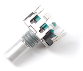
A typical rotary encoder - this one is from Adafruit.
This article describes a simple demo project based on an ATtiny85, using the rotary encoder to adjust the brightness of an LED:
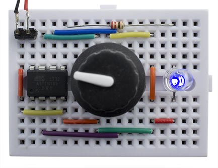
Demo ATtiny85 project using a rotary encoder to adjust the brightness of an LED.
For this example I used a basic rotary encoder available from Adafruit [1], or from The Pi Hut in the UK [2], which gives 24 pulses per rotation. I also tested it with Sparkfun's rotary encoder [3], which gives 12 pulses per rotation; it's available in the UK from Proto-PIC [4] or HobbyTronics [5]. Both of these rotary encoders also incorporate a switch that's activated when you press the knob. They can be persuaded to fit in a breadboard, but you may have to cut off the metal tabs on each side of the body.
Circuit
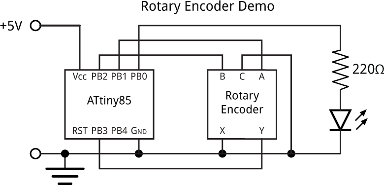
Here's the circuit of the demo rotary encoder interface. It allows you to vary the brightness of an LED by rotating the encoder. The push switch on the encoder switches the LED between its current brightness and off:
Demo ATtiny85 project uses a rotary encoder to adjust the brightness of an LED.
The rotary encoder outputs are connected to PB1 and PB2, and the push button is connected to PB3.
The program
The best way to read the rotary encoder is via an interrupt service routine, as this will ensure that you don't miss changes even when your main program is busy doing something else. The interrupt service routine can also check the push-button switch. In fact, a single interrupt-service routine could handle two or more encoders, for applications where you're controlling several things with different encoders.
First, pin change interrupts are set up on each of the rotary encoder inputs, so the interrupt service routine will be called whenever any of the inputs change:
void setup() {
  pinMode(LED, OUTPUT);
  pinMode(EncoderA, INPUT_PULLUP);
  pinMode(EncoderB, INPUT_PULLUP);
  pinMode(EncoderSwitch, INPUT_PULLUP);
  // Configure pin change interrupts
  PCMSK = 1<<EncoderA | 1<<EncoderSwitch;
  GIMSK = 1<<PCIE;                       // Enable interrupt
  GIFR = 1<<PCIF;                        // Clear interrupt flag
}
Here's the full definition of the interrupt service routine, which also handles an interrupt from the push switch. Variables a, b, and s hold the current states of the two rotary encoder inputs and switch, the global variable a0 holds the previous state of a, c0 holds the cleaned-up signal, and s0 holds the previous state of s:
ISR (PCINT0_vect) {
  int a = PINB>>EncoderA & 1;
  int b = PINB>>EncoderB & 1;
  int s = PINB>>EncoderSwitch & 1;
  if (a != a0) {              // A changed
    a0 = a;
    if (b != c0) {
      c0 = b;
      ChangeValue(a == b);
    }
  } else if (s != s0) {
    s0 = s;
    ChangeSwitch();
  }
}
This calls ChangeValue() when the encoder is rotated, or ChangeSwitch() when the encoder switch is pushed or released.
In my demo application ChangeValue() simply changes the brightness of an LED:
void ChangeValue (bool Up) {
  Brightness = max(min(Brightness + (Up ? 1 : -1), 510), 0);
  analogWrite(LED, (Brightness+1)/2);
}
ChangeSwitch() switches the LED off:
void ChangeSwitch () {
  Brightness = 0;
  analogWrite(LED, 0);
}
I compiled the program using Spence Konde's ATTiny Core [6]. Select the ATtiny x5 series option under the ATtinyCore heading on the Boards menu. Then choose Timer 1 Clock: CPU, B.O.D. Disabled, ATtiny85, 1 MHz (internal) from the subsequent menus; this is the default fuse setting on a new ATTiny85. Then upload the program using ISP (in-system programming); I used Sparkfun's Tiny AVR Programmer Board; see ATtiny-Based Beginner's Kit.
Here's the whole Rotary Encoder Demo program: Rotary Encoder Demo Program.
Update
28th October 2017: Since writing this I've realised that there is a simpler and better way of decoding a rotary encoder, as described in Bounce-Free Rotary Encoder, so I've updated this article to use the new procedure.
- ^ Rotary Encoder + Extras on Adafruit
- ^ Adafruit Rotary Encoder + Extras on The Pi Hut
- ^ Rotary Encoder on Sparkfun.
- ^ Rotary Encoder on Proto-PIC.
- ^ Rotary Encoder on HobbyTronics.
- ^ ATTinyCore on GitHub.
blog comments powered by Disqus