Scrolling Text Display
11th September 2024
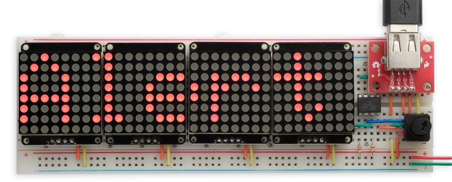
This is a scrolling text display based on four 8x8 LED dot-matrix displays, and controlled by an ATtiny85:

The Scrolling Text Display, based on an ATtiny85.
It includes a USB socket, so you can plug in a PS/2-compatible USB keyboard to allow you to enter and edit the message, and a potentiometer that allows you to adjust the scroll speed.
It could be used as an advertising sign, such as in a shop window, or as a message board to allow you to leave messages for your partner or housemates.
Updates
11th October 2024: Released v2 of the program that fixes a bug that could cause junk characters to appear on the end of a message.
24th September 2024: Added infomation about a second compatible keyboard.
12th September 2024: Added a note about using jumper wires in construction.
Introduction
I was inspired to build this for a friend's son who is keen on trains, to allow him to make a scrolling train sign like the ones used on many trains and platforms. It uses an external keyboard to allow you to enter a message of up to 256 characters. While you're entering the message the last few characters are shown on the display, and you can press Backspace to delete back to correct mistakes.
When you've entered the message you can press Enter, and the whole message will then start scrolling repeatedly across the display. A five-space gap is inserted between the end of one presentation and the start of the next. While the message is scrolling you can adjust the speed using the potentiometer.
Pressing Esc at any time returns to editing mode, and you can then edit starting at the end of the existing message, or press Tab to clear the message and enter a new message.
When you press Enter the message is stored in EEPROM, so if you disconnect the power and reconnect it, the last message will continue scrolling on the display. This allows you to detach the keyboard if you don't want to change the message.
The circuit
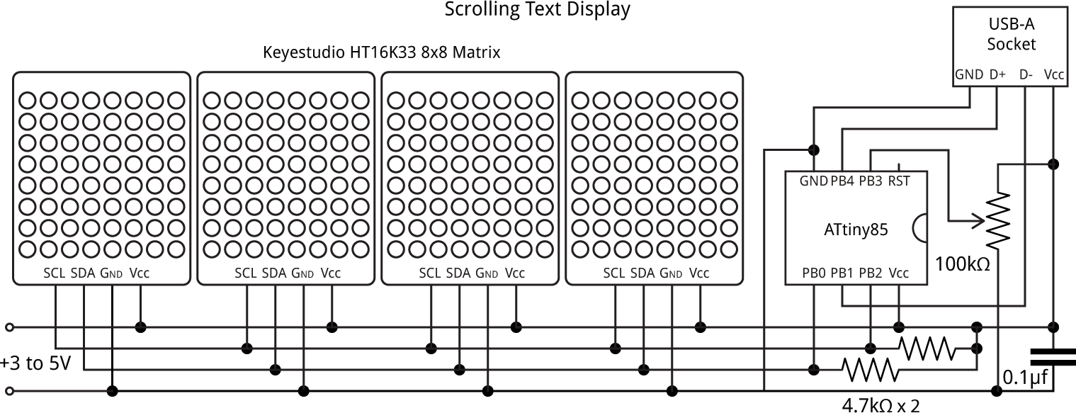
Here's the circuit of the Scrolling Text Display:

Circuit of the Scrolling Text Display.
Processor
I decided to base the circuit on an old favourite: the 8-pin ATtiny85. One reason is that it's available in a PDIP package and so it's easy to mount on the breadboard. It's also a perfect fit for this application. It has 512 bytes of RAM and 512 bytes of EEPROM, ample for the message buffer and for saving the message. It also has just the right number of spare pins: two for the I2C interface to the displays, two for the clock and data lines from the keyboard, and one for the ADC input from the potentiometer.
I considered using one of the newer 0-series or 1-series 8-pin devices, such as the ATtiny402 or ATtiny412, but these are only available in a surface-mount package and so would have to be mounted on a breakout board. In addition, they only have 256 bytes of RAM and 128 bytes of EEPROM, which would restrict the Scrolling Text Display to a much shorter message.
Displays
For the displays I used four low-cost Keyestudio I2C displays, which incorporate a HT16K33 driver chip [1] to handle the display multiplexing and I2C interface, allowing you to control them with just two I/O lines [2]. Adafruit make a similar display [3]. Three solder links allow you to choose one of eight I2C addresses for each display, allowing you to drive up to eight displays simultaneously. The Keyestation modules have got the labels for A1 and A2 swapped around on the PCB, so the addresses you get with the eight possible PCB link settings are as follows:
| A2 | A1 | A0 | Address |
| 0x70 (112) | |||
| X | 0x71 (113) | ||
| X | 0x74 (116) | ||
| X | X | 0x75 (117) | |
| X | 0x72 (114) | ||
| X | X | 0x73 (115) | |
| X | X | 0x76 (118) | |
| X | X | X | 0x77 (119) |
You can use any addresses for the four displays, provided they're different. The array Addresses[] specifies the sequence, from left to right; for example:
int Addresses[] = {112, 113, 116, 117};
Potentiometer
The potentiometer allows you to adjust the scrolling speed. It can be any value from 10kΩ to 100kΩ, or you can omit it and make a small change to the program if you don't want to make the scroll speed adjustable. A suitable 50kΩ breadboard-compatible trimmer is available from The Pi Hut [4].
Keyboard
Although it would be possible to interface a USB keyboard using a USB Host keyboard interface, this would require a more powerful processor capable of running TinyUSB [5]; current processors supported are the nRF52, ATSAMD21/51, RP2040, and ESP32. Fortunately many USB keyboards include support for the older PS/2 interface, and this uses a much simpler protocol that can be decoded by a processor such as the ATtiny85. Before buying a keyboard, check that it supports PS/2.
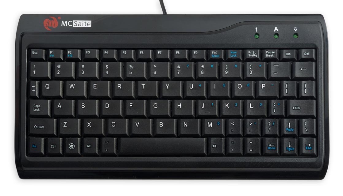
The one I used is the 220 x 118mm MC Saite MC-8017 Miniature PS/2 and USB keyboard, available from Adafruit [6], which is fitted with a USB-A plug:

MC Saite MC-8017 Miniature PS/2 and USB keyboard.
I've tested the project with a slightly larger low-cost 284 x 122mm Slim Chiclet Keyboard [7], which also also supports PS/2 codes, but note that it doesn't work below 3.5V.
Power
I powered the Scrolling Text Display using a switched battery box that holds two 1.5V AA batteries [8], but you can use any power source that provides between 3V and 5V.
Construction
To make building the Scrolling Text Display as easy as possible I designed it to fit on a full-sized breadboard [9], using through-hole components. To fit the displays onto the breadboard I cut off the right-angle headers supplied on the displays, and soldered straight headers in their place.
I find that the easiest way to wire up breadboards like this is using a set of precut jumper wires of different lengths [10]; the shorter lengths are coded by length using the resistor colour code. The displays are interconnected using links on the breadboard under the displays.
For the USB-A socket I used a breakout board from Sparkfun [11], because the through-hole sockets aren't breadboard friendly.
The program
Keyboard interface
The keyboard interface is based on my Simple PS/2 Keyboard Interface. PS/2 keyboards use a two-wire serial protocol, using a clock pin and a data pin.
My original routine used the PS/2 clock input to generate an INT0 interrupt on each falling edge. On the ATtiny85 the INT0 input is already in use for the I2C interface SCL pin, so I used a pin-change interrupt on the PB4 input instead. To ensure that we only respond to falling edges I added the following line to the start of the interrupt-service routine:
if (PINB & 1<<ClockPin) return;
Here's the whole interrupt-service routine:
ISR(PCINT0_vect) {
  static uint8_t Break = 0, Modifier = 0, Shift = 0;
  static int ScanCode = 0, ScanBit = 1;
  if (PINB & 1<<ClockPin) return;               // Only respond to a falling edge
  if (PINB & 1<<DataPin) ScanCode = ScanCode | ScanBit;
  ScanBit = ScanBit << 1;
  if (ScanBit != 0x800) return;
  // Process scan code
  if ((ScanCode & 0x401) != 0x400) return;      // Invalid start/stop bit
  int s = (ScanCode & 0x1FE) >> 1;
  ScanCode = 0, ScanBit = 1;
  if (s == 0xAA) return;                        // BAT completion code
  //
  if (s == 0xF0) { Break = 1; return; }
  if (s == 0xE0) { Modifier = 1; return; }
  if (Break) {
    if ((s == 0x12) || (s == 0x59)) Shift = 0;
    Break = 0; Modifier = 0; return;
  }
  if ((s == 0x12) || (s == 0x59)) Shift = 1;
  if (Modifier) return;
  char c = pgm_read_byte(&Keymap[s + KeymapSize*Shift]);
  if (c == 32 && s != 0x29) return;
  ProcessKey(c);
  return;
}
The PS/2 data output is connected to PB1, and the data consists of a '0' start bit, eight data bits, a parity bit, and a '1' stop bit. This then needs to be converted to an ASCII character using a lookup table, Keymap[] to cater for the rather haphazard arrangement of codes on PS/2 keyboards:
const uint8_t Keymap[] PROGMEM =
// Without shift
"             \011`      q1   zsaw2  cxde43   vftr5  nbhgy6   mju78  ,kio09"
"  ./l;p-   \' [=    \015] \\        \010  1 47   0.2568\033  +3-*9      "
// With shift
"             \011~      Q!   ZSAW@  CXDE$#   VFTR%  NBHGY^   MJU&*  <KIO)("
"  >?L:P_   \" {+    \015} |        \010  1 47   0.2568\033  +3-*9       ";
For details of the PS/2 keyboard Scan Code Set 2 encoding used by most keyboards see PS2 Keyboard Scan Codes.
Processing keys
When a keypress has been decoded the interrupt-service routine calls ProcessKey() to handle it:
void ProcessKey (char c) {
  if (c == 27) {                                // Escape key goes to edit mode
    DisplayMode = false;
    Scroll = 6 * max(WritePtr-5, 0);
    MessageChars = MessageSize;
    return;
  }
  if (DisplayMode) return;                      // Ignore all other keys
  // Edit buffer
  if (c == '\r') {                              // Return key goes to display mode
    DisplayMode = true;
    MessageChars = WritePtr + EndMessageGap;
    EEPROM.write(0, WritePtr);
    EEPROM.write(1, MessageChars);
    EEPROM.put(2, KybdBuf);                     // Save our message
    return;
  }
  if (c == 9) {                                 // Tab key
    for (int i=0; i<WritePtr+EndMessageGap; i++) KybdBuf[i] = ' ';
    WritePtr = 0;
  } else if (c == 8) {                          // Backspace key
    if (WritePtr > 0) {
      if (WritePtr <= 5) Scroll = Scroll - 6;
      WritePtr--;
      KybdBuf[WritePtr] = ' ';
    }
  } else if (WritePtr < MessageSize) {
    KybdBuf[WritePtr++] = c;
  }
  Scroll = 6 * max(WritePtr-5, 0);
  return;
}
In display mode, when DisplayMode is true, the scolling message is displayed and the only key that the program responds to is Esc (code 27) This switches back to edit mode, with the cursor positioned at the end of the previous message.
In edit mode characters are entered into an edit buffer, KybdBuf[], large enough to hold a 256-character message plus a gap of 5 spaces between messages. Pressing Enter at any time saves the edit buffer in EEPROM, and switches back to display mode. In edit mode the Tab key (code 9) clears the whole message, or the Backspace key (code 8) deletes the last character in the edit buffer.
Setup
The setup() routine initialises the keyboard interface, and sets up the four displays. The display brightness is controlled by the variable Brightness which can be set to between 1 and 15, but I found that a setting of 2 was amply bright. It then initialises the message from EEPROM. When you first build the project this will be random characters; press Enter and Tab to clear the message.
The main loop
The main loop continuously refreshes the displays from the keyboard buffer:
void loop() {
  for (int disp=0; disp<4; disp++) {
    for (int c=0; c < 8; c++) {
      int dcol = disp*8 + c;
      int column = dcol + Scroll;
      int nchar = (column/6)%MessageChars;
      int cchar = column%6;
      int addr = Addresses[disp];
      Wire.beginTransmission(addr);
      Wire.write(c<<1);
      int segs = ReverseByte(pgm_read_byte(&CharMap[KybdBuf[nchar]-32][cchar]));
      Wire.write(segs>>1 | segs<<7);
      Wire.endTransmission();
    }
  }
  delay(analogRead(ADCPin)>>3);
  if (DisplayMode) Scroll++;
}
In edit mode it displays the last five characters in the keyboard buffer.
In display mode it increments the variable Scroll, which scrolls the display by one pixel each time round the loop. The delay between scrolls is determined by a value read from the analogue input connected to the potentiometer, allowing you to adjust the scroll speed.
Compiling and uploading
Compile the program using Spence Konde's ATTiny Core [12]. Choose the ATtiny25/45/85 (No bootloader) option under the ATTinyCore heading on the Board menu. Then check that the subsequent options are set as follows (ignore any other options):
Chip: "ATtiny85"
Clock Source (Only set on bootload): "8 MHz (internal)"
Connect to the appropriate ATtiny85 pins on the breadboard using an ISP programmer; I used Sparkfun's Tiny AVR Programmer Board; see ATtiny-Based Beginner's Kit. The connections are as follows:
| Programmer | ATtiny85 |
| Reset | RST (pin 1) |
| MOSI | PB0 (pin 5) |
| MISO | PB1 (pin 6) |
| 5V | VCC (pin 8) |
| SCK | PB2 (pin 7) |
| GND | GND (pin 4) |
Set Programmer to USBtinyISP (ATTinyCore) SLOW (or whatever's appropriate for your programmer). Choose Burn Bootloader on the Tools menu to set the fuses appropriately. Then choose Upload on the Sketch menu to upload the program.
To test the program you need to disconnect the programmer from the MOSI pin, as it interferes with the I2C interface.
Resources
Here's the whole program: Scrolling Text Display program.
I'm working on a printed circuit board for the project, and hope to publish details in a future article.
- ^ HT16K33 Datasheet on Adafruit.
- ^ Keyestudio I2C 8x8 LED Matrix on AliExpress.
- ^ Mini 8x8 LED Matrix w/I2C Backpack on Adafruit.
- ^ Breadboard-friendly Trim Potentiometer on The Pi Hut.
- ^ Arduino library for TinyUSB on GitHub
- ^ Miniature PS/2 and USB keyboard on Adafruit.
- ^ Slim Chiclet Keyboard on Pimoroni.
- ^ Switched Battery Box 2xAA (3V) on The Pi Hut.
- ^ Full Sized Premium Breadboard - 830 Tie Points on Adafruit.
- ^ Jumper Wires, 140 Pack Assorted on CPC.
- ^ USB Type A Socket Breakout on Sparkfun.
- ^ ATTinyCore on GitHub.
blog comments powered by Disqus
