10 or 12-bit DAC from the ATtiny85
2nd April 2017
This article describes how to get up to two 10 or 12-bit digital-to-analogue outputs from an 8-bit Timer/Counter, such as in the ATtiny85. To test the routine I built a circuit which allows you to vary the brightness of two LEDs with two potentiometers:
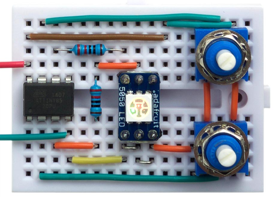
Demonstration of two 12-bit digital-to-analogue outputs on the ATtiny85.
Introduction
The ATtiny85 provides two 8-bit Timer/Counters, so the digital-to-analogue PWM output it can produce is only 8-bit resolution. Sometimes, though, 8 bits isn't enough. For example, using an 8-bit DAC to vary the brightness of an LED will give noticable steps in brightness at the lower brightness levels. And, using it to create a variable voltage output gives you steps of about 0.02V, which may not be fine enough for a variable power supply.
One solution is to choose a processor with a 16-bit Timer/Counter, such as the ATtiny84. However, you may already be committed to using the ATtiny85, or like me, like to use the smallest possible processor for any application, so I decided to try and get a 10 or 12-bit analogue output from the ATtiny85.
Pulse-Width Modulation
The way that Pulse-Width Modulation, or PWM works is that it divides the period of the output waveform into equal time slots. An analogue voltage is generated by varying the proportion of the time that the output pin is at Vcc, compared to the amount of time it is at 0V.
For example, with 8-bit PWM there are 256 time slots. If we want to convert the number 64, the output is high for 64 slots and low for the remaining 192 time slots, and the output voltage will, on average, be 64/256 * 5V, or 1.25V. To achieve the "on average" we can either connect a capacitor across the output, to smooth the pulses, or when driving an LED, if the frequency is fast enough, the eye smooths the pulses to give the appearance of a continuous, dim light.
Note that the arrangement of pulses in the 256 time slots is irrelevant - all that matters is the proportion of the time that the output is high.
PWM on the ATtiny85
First let's review how you get an 8-bit digital-to-analogue conversion on the ATtiny85 using PWM. Here I use Timer/Counter1, for two reasons. Firstly, it leaves Timer/Counter0 free for use by the Arduino functions millis() etc. Secondly, the PWM in Timer/Counter1 has the feature that values of 0 and 255 set the output continuously low or continuously high respectively. This is a key part of the following routines.
Here's how to get Timer/Counter1 to output the value 64 to PB1:
void setup() {
  // Timer/Counter1 doing PWM on OC1A (PB1)
  TCCR1 = 1<<PWM1A | 1<<COM1A0 | 1<<CS10;
  pinMode(1, OUTPUT);
}

void loop () {
  OCR1A = 64;
  delay(100);
}
One 10-bit analogue output
Here's a routine to get a single 10-bit analogue output:
// One 10-bit analogue output from an ATtiny85 ************************************

volatile int Dac = 0;
volatile int Cycle = 0;

// Overflow interrupt
ISR (TIMER1_OVF_vect) {
  static int remain;
  if (Cycle == 0) remain = Dac;
  if (remain >= 256) { OCR1A = 255; remain = remain - 256; }
  else { OCR1A = remain; remain = 0; }
  Cycle = (Cycle + 1) & 0x03;
}

void analogWrite10 (int value) {
  cli(); Dac = value; sei();
}

void setup() {
  // Timer/Counter1 doing PWM on OC1A (PB1)
  TCCR1 = 1<<PWM1A | 1<<COM1A0 | 1<<CS10;
  TIMSK = TIMSK | 1<<TOIE1;
  pinMode(1, OUTPUT);
}

void loop () {
  int value = analogRead(A1);
  analogWrite10(value);
  delay(100);
}
This routine uses the overflow interrupt on Timer/Counter1 to change the value in the compare match register, OCR1A, every 256 cycles. The time taken to calculate the new value is not a problem because the Timer/Counter buffers the OCR1A and OCR1B registers in PWM mode, so we have 256 cycles within which to set the next compare match value.
To use the routine you call analogWrite10() with a number between 0 and 1023.
The routine takes advantage of the fact that, on Timer/Counter1, setting OCR1A to 255 keeps the output high; ie gives a value of 256. For each set of four successive overflow interrupts we repeat the following:
- If it's the first cycle set remain to the Dac value.
For each cycle we then do:
- If remain is greater than or equal to 256, set OCR1A to 255, and subtract 256 from remain.
- Otherwise set OCR1A to remain and set remain to 0.
This outputs a repeating sequence of four values which sum to the Dac value. For example, calling the routine with the value 520 outputs:
256, 256, 8, 0
The program in loop() demonstrate the routine by calling analogRead() to read a 10-bit value from a potentiometer, and set the output PB1 accordingly.
Two 12-bit analogue outputs
You can extend the above technique to use the two compare match registers in Timer/Counter1 to give two 12-bit analogue outputs:
// Two 12-bit analogue outputs from an ATtiny85 ************************************

volatile int Dac[2];
volatile uint8_t* Port[] = { &OCR1A, &OCR1B };
volatile int Cycle = 0;

// Overflow interrupt
ISR (TIMER1_OVF_vect) {
  static int rem[2];
  for (int chan=0; chan<2; chan++) {
    int remain;
    if (Cycle == 0) remain = Dac[chan]; else remain = rem[chan];
    if (remain >= 256) { *Port[chan] = 255; remain = remain - 256; }
    else { *Port[chan] = remain; remain = 0; }
    rem[chan] = remain;
  }
  Cycle = (Cycle + 1) & 0x0F;
}

void analogWrite12 (int chan, int value) {
  cli(); Dac[chan] = value; sei();
}

void setup() {
  // Timer/Counter1 doing PWM on OC1A (PB1) and OC1B (PB4)
  TCCR1 = 1<<PWM1A | 1<<COM1A0 | 1<<CS10;
  GTCCR = 1<<PWM1B | 1<<COM1B0;
  TIMSK = TIMSK | 1<<TOIE1;
  pinMode(1, OUTPUT);
  pinMode(4, OUTPUT);
}

void loop () {
  int value = 0;
  for (int i=0; i<4; i++) value = value + analogRead(A1);
  analogWrite12(0, value);
  value = 0;
  for (int i=0; i<4; i++) value = value + analogRead(A3);
  analogWrite12(1, value);
  delay(100);
}
For each of the two Dac[] values this outputs a repeating sequence of 16 values which sum to the value.
To use the routine you call analogWrite12() with the output number 0 (for PB1) or 1 (for PB4), and a 12-bit number between 0 and 4095. Using an ATtiny85 with a 1Mhz internal clock the PWM frequency is about 244Hz, high enough for driving LEDs without flicker.
The program in loop() demonstrates the routine by summing four successive values from a potentiometer on A1 (PB2), to give a 12-bit value from 0 to 4095, and then writes it to PB1. It then does the same for a potentiometer on A3 (PB3), and writes it to PB4. The circuit I used is as follows:
Circuit to test two 12-bit digital-to-analogue outputs on the ATtiny85.
blog comments powered by Disqus