I2C GPS Module PCB
15th November 2018
This is a compact GPS module with an I2C interface, making it easy to read the GPS parameters from another project without needing to worry about parsing the NMEA sentences. It's a PCB-mounted version of my earlier project I2C GPS Module:
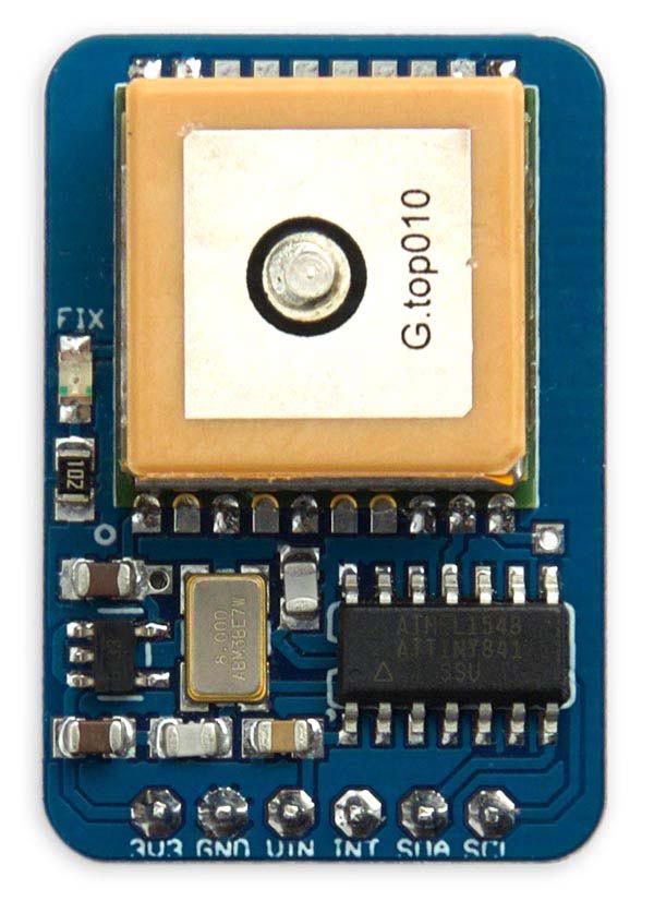
The I2C GPS Module based on an ATtiny841 and a GTPA010 GPS module.
As an example of using the module I also describe a GPS mapping application, that plots a map of your route on an OLED display.
I based the PCB on the GlobalTop Technology FGPMMOPA6C GPS module, also known as the GTPA010 [1], and these are available from AliExpress [2]. It should also work with more recent versions of that module, such as the PA6H available from Adafruit [3]. The GPS module is rated at 3.3V so I included a 3.3V regulator on the board so you can power the board from 3.3V or 5V.
The NMEA sentences are decoded by an ATtiny841, and this also runs the I2C slave routine.
GPS variables
To read the GPS data you write one byte to specify the offset of the first variable you want to read, and then read the appropriate number of bytes corresponding to the values you want to read. For example, to read just the latitude and longitude you'd write 4 and then read 8 bytes.
The 18 bytes in the I2C data contain the raw GPS data extracted from the NMEA message:

These variables are as follows:
| Offset | Variable | Description |
| 0 | Time | The time in HH:MM format. |
| 2 | Csecs | The seconds in centiseconds. |
| 4 | Lat | The latitude in units of 1e-4 arc minutes. |
| 8 | Long | The longitude in units of 1e-4 arc minutes. |
| 12 | Knots | The speed, in 1e-2 knots. |
| 14 | Course | The course or track, in 1e-2 degrees. |
| 16 | Date | The date in DD:MM format. |
The angular measures, latitude and longitude, are returned in units of 1e-4 arc minutes. Thus one degree is represented as 600,000 units. This is designed to allow the arithmetic to be done using long integers, and is ideal for parsing the values returned by the GPS module without any loss of accuracy.
- If you prefer to work with the latitude and longitude in millionths of a degree, like some other GPS libraries, simply multiply by 5/3.
- If you want to work with the latitude and longitude as floating-point numbers, in degrees, divide them by 6e5.
- If you want to work with the latitude and longitude as degrees, arc minutes, and arc seconds use the calculations in the demo program below.
Circuit
Here's the circuit:
Circuit of the I2C GPS Module, based on an ATtiny841.
SDA and SCL are the I2C connections. INT is an optional interrupt output that goes low when data is ready to be read, and is cleared by reading data via I2C. Power should be supplied to VIN, which can take between 5V and 3.3V, and GND.
The 3.3V pin is an optional output, provided in case you want to power other 3.3V devices.
The board will cater for microcontrollers that are either 5V or 3.3V:
- If you are connecting this to a microcontroller with 5V signals, like an Arduino Uno, provide 5V to VIN, so the SCL and SDA signals are at a 5V level. The Tx signal from the GPS module to the ATtiny841 will be at 3.3V levels, but this is within specification for 5V logic.
- If your microcontroller has 3.3V signals, like an Arduino Zero, provide 3.3V to VIN so the SCL and SDA signals are at a 3.3V level.
Depending on what you're connecting the I2C GPS module to you may need pullup resistors of about 4.7kΩ between the SDA and SCL lines and Vcc. I found I didn't need them connecting the module to an Arduino Uno, but did need them with an Aduino Zero.
► Parts list
Construction
I designed a board in Eagle and sent it to PCBWay for fabrication [4]. There's a link to the Eagle files at the end of the article if you want to make yourself a board. Here's a preview of the front and back of the PCB from the OSH Park service:
The ATtiny841 is in an SOIC package, and the resistors, capacitor, and LED are all 0805 size, so they should be relatively easy to solder by hand. The crystal is 5x3mm, and the regulator is in an SOT32-5 package.
I recommend only soldering the tabs of the GPS module that are connected, to make it easier to remove the module at a later date if you need to.
The program
For details of the code see my earlier article I2C GPS Module.
Compiling the program
I compiled the program using Spence Konde's ATTiny Core [5]. Choose the ATtiny441/841 (No bootloader) option under the ATtinyCore heading on the Board menu. Then choose ATtiny841, 8 MHz (external), B.O.D. Disabled from the subsequent menus.
I connected to the ATtiny841 using a Pomona test clip that fitted to the top of the chip [6], using the Sparkfun Tiny AVR Programmer [7]. Choose Burn Bootloader to set the fuses appropriately, then choose Upload to upload the program.
Here's the whole I2C GPS Module program: I2C GPS Module Program.
Alternatively, get it on GitHub here together with the Eagle files for the PCB: I2C GPS Module on GitHub.
Or order yourself a board from OSH Park here: I2C GPS Module.
GPS mapping application
Here's an example to demonstrate a simple application of the I2C GPS Module. It plots the GPS position to a monochrome 128x64 OLED display, so as you walk around it shows a track of your route. I initially wrote and tested the example program in uLisp, my Lisp interpreter for microcontrollers; for details of the Lisp version see GPS Mapping Application on uLisp. I then converted this to the C program described below.
I ran the program on an Adafruit ItsyBitsy M4 [8], which is compact enough to fit on two mini breadboards along with the OLED display and GPS module:
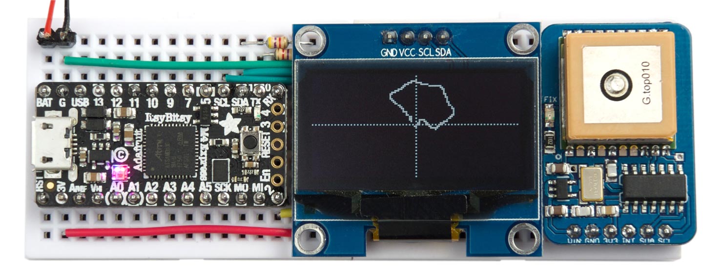
A walk around the block plotted using the GPS Mapping application.
The C version should compile and run on any Arduino board, down to an Arduino Uno.
The circuit
Here's how everything's interconnected:
Circuit of the GPS Mapping application.
Of, course, if you don't want to make a PCB you can use this application with the breadboard version, I2C GPS Module.
The display needs to be a monochrome 128x64 OLED display based on the SH1106 driver chip; for example, the Geekcreit 1.3" I2C OLED display, available from Banggood [9]. The SH1106 driver chip supports reading back the display memory, which is essential for plotting a single point without affecting the neighbouring points.
Converting latitude and longitude to x and y
The main part of the program reads the latitude and longitude from the I2C GPS module, converts them to x,y coordinates, and plots them as a point on the display.
For small distances we can assume that the surface of the earth is flat and use the following formulae:
x = R ⋅ λ ⋅ cos (φ)
y = R ⋅ φ
where φ is the latitude in radians, λ is the longitude in radians, and R is the earth's mean radius, 6371km.
Here's the routine ReadPosition() that reads the latitude and longitude bytes from the I2C GPS module, converts them to x and y coordinates, and stores them in x and y:
void ReadPosition (float *x, float *y) {
  Wire.beginTransmission(0x3A);
  Wire.write(4);                                 // Start with latitude
  Wire.endTransmission();
  Wire.requestFrom(0x3A, 8);                     // Ask for 8 bytes
  long Lat = 0, Long = 0;
  for (int i=0; i<4; i++) Lat = Lat | (long)Wire.read()<<(i*8);
  for (int i=0; i<4; i++) Long = Long | (long)Wire.read()<<(i*8);
  *x = R * Radians(Long/6e5) * cos(Radians(Lat/6e5));
  *y = R * Radians(Lat/6e5);
}
This uses the following routine, Radians(), to convert from degrees to radians:
float Radians (float deg) {
  return deg * asin((float)1) / 90;
}
The variable R is the radius of the earth, in metres:
const float R = 6.371e6;
Plotting the path
The main program first initialises and clears the display in setup(), and waits until the GPS module has obtained a fix. It then draws the crosshairs, indicating the starting position, xHome, yHome:
void setup() {
  Wire.begin();
  InitDisplay();
  ClearDisplay();
  while(digitalRead(2) == 1);                    // Wait for fix
  Cross();
  ReadPosition(&xHome, &yHome);
}
The main loop() then plots points relative to the starting position, which is centred on the centre of the display:
void loop() {
  float xHere, yHere;
  ReadPosition(&xHere, &yHere);
  int dx = round((xHere - xHome)/10);
  int dy = round((yHere - yHome)/10);
  PlotPoint(dx+64, dy+32);
  while(digitalRead(2) == 1);
}
With these figures each pixel represents 10m, so the whole display represents an area 1280 x 640m.
Here's the whole I2C GPS mapping application: I2C GPS Mapping Application.
Further suggestions
If you go beyond the area represented by the display the plotting will give unpredictable results, so it would be better to test that the x and y values are within range.
With a bit more work this program could form the basis for a GPS treasure-hunt project, or a hiking companion.
- ^ PA6C (MTK3339) GPS module datasheet on Adafruit.
- ^ GTPA010 MT3339 PA6C GPS Standalone Module on AliExpress.
- ^ Ultimate GPS module - 66 channel w/10 Hz updates - MTK3339 chipset on Adafruit.
- ^ PCBWay PCB prototyping service.
- ^ ATTinyCore on GitHub.
- ^ IC Test Clip SOJ SOIC 14 Contacts on Farnell.
- ^ Tiny AVR Programmer on Sparkfun.
- ^ Adafruit ItsyBitsy M4 Express featuring ATSAMD51 on Adafruit.
- ^ Geekcreit 1.3 Inch 4 Pin White OLED LCD Display on Banggood.
blog comments powered by Disqus