Making Your Own I2C Peripherals
6th August 2016
A typical microcontroller project involves connecting input devices, displays, and sensors to a microcontroller. One approach is to get a processor with enough I/O lines to connect all the devices, and then write code, or load a library, to interface to each of the devices.
An alternative approach is to use a low-cost processor to make each peripheral into an I2C device. You can then connect them all to the same two-wire I2C bus, and the only code you need to interface to them is a standard I2C library.
This article shows how to make a simple I2C display module which allows you to control a 2-digit 7-segment display over the I2C bus:
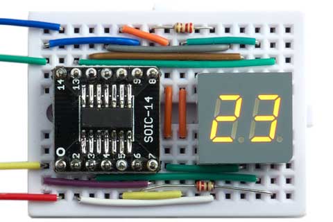
I2C display module based on an ATtiny841.
The design could be used as the basis for other I2C devices that receive data from an I2C master, send data to an I2C master, or a combination of the two. It is based on the ATtiny841 (or ATtiny441) processor, an updated version of the popular ATtiny84 with better hardware I2C support.
ATtiny I2C support
In most ATtiny chips, such as the ATtiny85, ATtiny84, and ATtiny2313, you can get I2C support using the hardware USI (Universal Serial Interface), which provides not much more than an 8-bit shift register to read in/out the address or data. With the USI you still need to do a lot of the work in software, so implementing I2C on these chips is quite laborious. There are libraries to do this, like Adafruit's TinyWireM [1].
The ATtiny48/88 is the odd one out - it provides a full TWI interface, identical to the one in the ATmega328, with both master and slave capability, so you can use the normal Arduino Wire library with this [2].
Finally, the newer ATtiny828 and ATtiny441/841 provide a TWI (Two-Wire Interface), which provides slave I2C capability in hardware. With these chips implementing an I2C slave is relatively easy, and one way is to use Orangkucing's WireS library [3]. I decided to use the ATtiny841 because I only wanted I2C slave capability, and it's a small 14-pin package with exactly the number of I/O pins I needed. I decided to implement the slave software myself, rather than use a library, with the aim of keeping it as simple as possible.
Circuit
Here's the circuit of the I2C display:
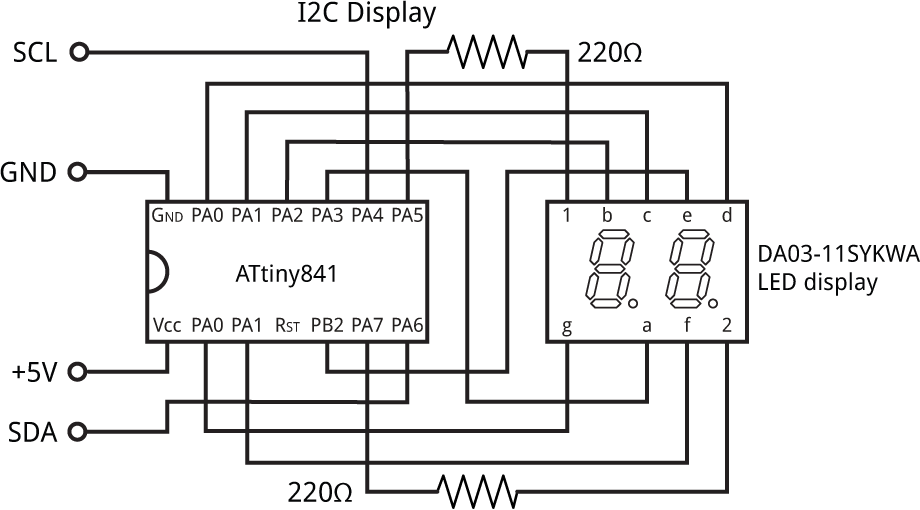
Circuit of the I2C display module.
For the display I used a Kingbright DA03-11SYKWA available from RS-Online in the UK [4], but any similar 2-digit display should work.
Unfortunately the ATtiny841 is only available in a SOIC package (please Atmel release the ATtiny841 in a PDIP package!) so I had to get a breakout board. Adafruit make a reasonably priced one [5]. The Adafruit site has a tutorial on using it [6].
The display and breakout board both fitted neatly on a mini breadboard, available from SparkFun [7] or HobbyTronics in the UK [8]. The wiring pretty much follows the layout on the above circuit.
I2C interface
I found the ATtiny841 datasheet quite hard to follow, and it took a lot of work to get the TWI interface to work correctly. After a bit of experimentation I decided that:
- For a simple application, we don't need to receive an interrupt when a Stop has been received, so TWSIE (TWI Stop Interrupt Enable) can be left as zero.
- We don't need to worry about bus errors or collisions, as these are generally handled automatically.
For this display application we only need to write from the master to the slave, but I also wanted to implement reading from the slave for future applications, so I included the facility to read back the display bytes.
The following line defines I2CAddress, the address of the I2C Slave; here it's 58 decimal:
const int I2CAddress = 0x3A;
Then, the following code in setup() configures the I2C interface:
// Set up as I2C slave
TWSCRA = 1<<TWDIE | 1<<TWASIE | 1<<TWEN;
TWSA = I2CAddress<<1;
TWASIE is set to specify that we want an interrupt on an address match, and TWDIE is set to specify that we want an interrupt when data has been received or transmitted. Note that in Master Read mode an extra data interrupt is generated to request the first byte of data.
Finally, here's the TWI interrupt service routine. Note that the vector name is TWI_SLAVE_vect, not TWI_vect as implied by the datasheet:
ISR(TWI_SLAVE_vect) {
  if (TWSSRA & 1<<TWASIF) {              // Address received
    if (TWSSRA & 1<<TWDIR) {             // Master read
      Read = 0;
      TWSCRB = 3<<TWCMD0;                // ACK
    } else {                             // Master write
      Write = 0;                         // Reset pointer
      TWSCRB = 3<<TWCMD0;                // ACK
    }
  } else if (TWSSRA & 1<<TWDIF) {        // Data interrupt
    if (TWSSRA & 1<<TWDIR) {             // Master read
      if (Read < 2) {
        TWSD = Buffer[Read++];
        TWSCRB = 3<<TWCMD0;
      } else TWSCRB = 2<<TWCMD0;         // Complete transaction
    } else {                             // Master write
      if (Write < 2) Buffer[Write++] = TWSD;
      if (Write < 2) TWSCRB = 3<<TWCMD0; // ACK
      else TWSCRB = 1<<TWAA | 2<<TWCMD0; // NACK and complete
    }
  }
}
The structure of this interrupt service routine is as follows:
- If the interrupt is caused by an address match:
- If it is a Master Read then zero the read pointer, and send an ACK.
- If it is a Master Write then zero the write pointer, and send an ACK.
- Otherwise the interrupt is a data interrupt:
- If the address indicated a Master Read and there are more bytes to send, put the next byte in the data register, otherwise end the transaction.
- If the address indicated a Master Write, read the next byte from the data buffer and display it, and send an ACK if we want to receive more bytes, otherwise a NACK.
Multiplexing the display
As in several of my previous projects, the display is generated under interrupt, using the contents of the array Buffer[]. For example, to display "AB" execute:
Buffer[0]=0xA; Buffer[1]=0xB;
The program uses Timer/Counter1 to generate an interrupt at 500Hz, which is used to multiplex the display. This leaves Timer/Counter0 free for use by the Arduino core functions Delay(), Millis() etc. This is configured by the following lines in setup():
// Set up Timer/Counter1 to multiplex the display
TCCR1A = 0<<WGM10;                     // CTC mode; count up to OCR0A
TCCR1B = 1<<WGM12 | 2<<CS10;           // Divide by 8
OCR1A = 249;                           // Compare match at 500Hz
TIMSK1 = TIMSK1 | 1<<OCIE1A;           // Enable compare match interrupt
The Timer/Counter1 interrupt service routine calls DisplayNextDigit() to write the appropriate segment data to the next display digit:
void DisplayNextDigit() {
  Digit = Digit ^ 1;                     // Toggle between 0 and 1
  int segs = charArray[Buffer[Digit]];
  DDRA = 0; DDRB = 0;                    // All inputs
  // Set display segments
  PORTA = 0; PORTB = 0;
  DDRB = segs & 0x07;                    // Outputs
  DDRA = (segs>>3) & 0x0F;
  DDRA = DDRA | 1<<Digits[Digit];        // Make it an output
  PORTA = PORTA | 1<<Digits[Digit];      // Make it high
}
Note that we don't need to mask out the SDA and SCL bits because enabling the TWI interface automatically disconnects these bits from the PORTA and DDRA registers.
Compiling the program
I compiled the program using Spence Konde's excellent new ATTiny Core, which now supports all the ATtiny processors and supersedes the various earlier ATtiny cores [9]. Select the ATtinyx41 option under the ATtiny Universal heading on the Boards menu. Then choose B.O.D. Disabled, ATtiny841, 1 MHz (internal) from the subsequent menus. This is the default fuse setting on new ATtiny841s; otherwise choose Burn Bootloader to set the fuses appropriately. Then upload the program to the ATtiny841 using the Tiny AVR Programmer Board; see ATtiny-Based Beginner's Kit.
Here's the whole I2C Display Module program: I2C Display Module Program.
Testing the display module
I tested the I2C display module using my uLisp interpreter running on an Arduino. For example, to display "23" execute the following uLisp command:
(with-i2c (str 58) (write-byte 2 str) (write-byte 3 str))
To read back the contents of the display buffer execute:
(with-i2c (str 58 2) (list (read-byte str) (read-byte str)))
This should print:
(2 3)
Update
22nd July 2017: Corrected mistakes in the above uLisp commands.
- ^ TinyWireM on GitHub.
- ^ Wire library on Arduino.cc.
- ^ WireS on GitHub.
- ^ Kingbright DA03-11SYKWA 2 Digit 7-Segment LED Display on RS-Online.
- ^ SMT Breakout PCB for SOIC-14 or TSSOP-14 on Adafruit.
- ^ SMT breadboard Prototyping Using Breakout PCBs on Adafruit.
- ^ Breadboard - Mini Modular on SparkFun.
- ^ Mini Breadboard from HobbyTronics.
- ^ ATTinyCore on GitHub.
blog comments powered by Disqus