Diffusion Clock
17th November 2020
This article describes a simple 12-hour clock, based on an ATtiny85 processor, using two I2C dot-matrix displays to show the time:
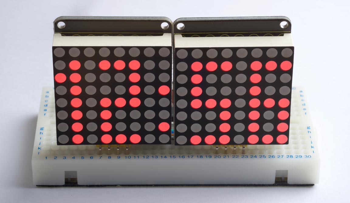
Diffusion Clock based on an ATtiny85.
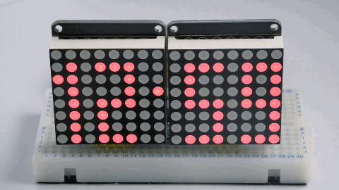
Every minute the display disappears randomly, a dot at a time, to a blank display, and then the new time appears a dot at a time, making it look as if the time diffuses between the two displays.
Introduction
You can fit four digits to display the time on two 8x8 dot matrix LED displays, using characters based on a 3x8 matrix, and there's even space left for a colon between the hours and minutes.
I used two Keyestudio I2C displays, which incorporate a HT16K33 driver chip [1] to handle the display multiplexing and I2C interface, allowing you to control them with just two I/O lines [2]. Adafruit make a similar display [3].
Three solder links allow you to choose one of eight I2C addresses for each display, allowing you to drive up to eight displays simultaneously. You can choose an address from 0x70 (112) to 0x77 (119), and the default I2C address with no links is 0x70 or 112.
The circuit
Here's the circuit:
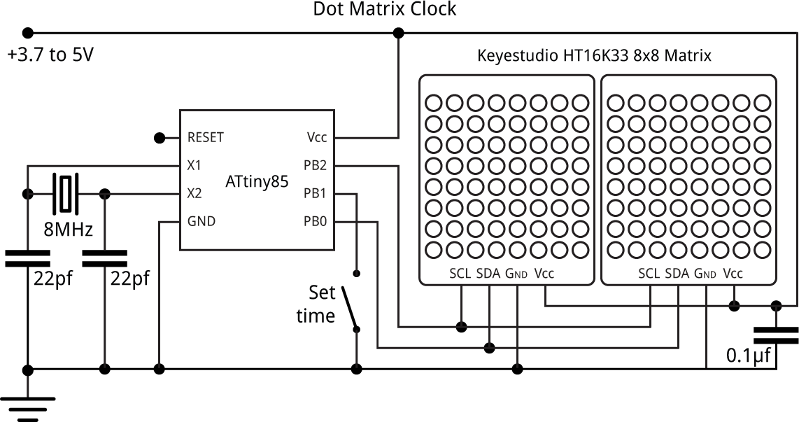
The crystal was an 8MHz through-hole type. A button connected to the spare input allows you to set the time.
The displays include pullup resistors on SCL and SDA, so you don't need to provide these in the circuit.
Construction
I built the circuit on a prototyping board, with the displays mounted vertically at the front of the board. Here's a view of the layout:
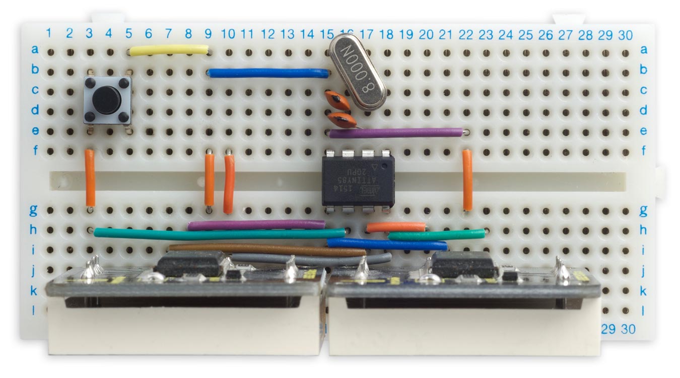
The clock was powered from a rechargeable 3.7V Lipo battery.
The program
I tested the idea by first writing a simpler version (without the diffusion effect) in uLisp, my Lisp interpreter for microcontrollers [4]. I then converted this into the following C program to run on the ATtiny85.
First we define the character definitions for the 3x8 digits, 0 to 9:
char CharMap[10][3] = {
{ 0x7F, 0x41, 0x7F }, // 0
{ 0x00, 0x20, 0x7F }, // 1
{ 0x4F, 0x49, 0x79 }, // 2
{ 0x49, 0x49, 0x7F }, // 3
{ 0x78, 0x08, 0x7F }, // 4
{ 0x79, 0x49, 0x4F }, // 5
{ 0x7F, 0x49, 0x4F }, // 6
{ 0x40, 0x40, 0x7F }, // 7
{ 0x7F, 0x49, 0x7F }, // 8
{ 0x79, 0x49, 0x7F }, // 9
};
The variables adr1 and adr2 are used to specify the addresses of the two displays:
const int addr1 = 117;
const int addr2 = 116;
The setupDisplay() and setBrightness() routines configure the HT16K33 display driver, and set the brightness which can be from 0 to 15:
void setupDisplay (int addr) {
  Wire.beginTransmission(addr);
  Wire.write(0x21);
  Wire.endTransmission();
  Wire.beginTransmission(addr);
  Wire.write(0x81);
  Wire.endTransmission();
}
void setBrightness (int addr, int bri) {
  Wire.beginTransmission(addr);
  Wire.write(0xe0 + bri);
  Wire.endTransmission();
}
The routine putColumn() writes the bit pattern for a single column (0 to 15) to the appropriate display:
void putColumn (int col, int bits) {
  int addr;
  if (col < 8) addr = addr1; else addr=addr2;
  Wire.beginTransmission(addr);
  Wire.write((col & 0x07)<<1);
  Wire.write(bits>>1 | bits<<7);
  Wire.endTransmission();
}
The expression:
bits>>1 | bits<<7
compensates for the fact that for some reason the rows of these displays are numbered in the sequence 7, 0, 1, 2, 3, 4, 5, 6 from bottom to top.
The routine copyDigit() copies the three columns for the character definition of a specified digit to three successive elements in the array columns[], starting at column col:
void copyDigit (int digit, int col, int columns[]) {
  for (int i=0; i<3; i++) columns[col+i] = CharMap[digit][i];
}
Finally showTime() displays the time, in hours and minutes, on the displays:
void showTime (int hours, int mins, int halfseconds) {
  int cols[16];                         // Dot matrix bitmaps
  // Hour tens
  if (hours/10 != 0) {
    cols[0] = CharMap[1][1]; cols[1] = CharMap[1][2];
  } else {
    cols[0] = 0; cols[1] = 0;
  }
  // Hour units
  cols[2] = 0;
  copyDigit(hours % 10, 3, cols);
  // Colon
  cols[6] = 0;
  if (halfseconds & 1) cols[7] = 0x02; else cols[7] = 0x10;
  // Minutes tens
  cols[8] = 0;
  copyDigit(mins / 10, 9, cols);
  // Minutes units
  cols[12] = 0;
  copyDigit(mins % 10, 13, cols);
  if (halfseconds == 119 && !ButtonDown()) {
    FadeOut(cols);
  } else if (halfseconds == 0 && !ButtonDown()) {
    FadeIn(cols);
  } else {
    // Plot time normally
    for (int col=0; col<16; col++) {
      putColumn(col, cols[col]);
    }
  }
}
Diffusion effect
The diffusion effect provides a transition each time the minutes change:
This is implemented using the following two routines:
The routine FadeOut() diffuses the previous display away to a blank display:
void FadeOut(int cols[]) {
  for (int i=0; i<127; i++) {
    int r = pseudoRandom();
    int col = r & 0xF;
    int bit = r>>4;
    cols[col] = cols[col] & ~(1<<bit);
    putColumn(col, cols[col]);
    delay(3); // Max. 3
  }
}
and the routine FadeIn() then diffuses in the new display:
void FadeIn(int cols[]) {
  int newcols[16];
  for (int i=0; i<16; i++) newcols[i] = 0;
  for (int i=0; i<127; i++) {
    int r = pseudoRandom();
    int col = r & 0xF;
    int bit = r>>4;
    newcols[col] = newcols[col] | (cols[col] & 1<<bit);
    putColumn(col, newcols[col]);
    delay(3); // Max. 3
  }
}
The bit to be changed is calculated using a pseudo-random number generator [5], which generates the numbers from 1 to 127 in a pseudo-random sequence [6]. Each number is used to select one of the dots, to give the appearance of a random sequence of changes:
int pseudoRandom () {
  static int r = 1;
  int l = r & 1;
  r = r>>1;
  if (l == 1) r = r ^ 0x69;
  return r;
}
Set time button
The Set Time button allows you to set the clock to the correct time. Holding it down steps through the hours twice a second. Releasing and pressing the button again then steps through the minutes twice a second.
The button uses I/O pin PB1, and is set up with an input pullup. The button is read by ButtonDown(), which returns true if the button is being pressed:
boolean ButtonDown () {
  return (digitalRead(1) == 0);                    // True if button pressed
}
The updateTime() routine is called twice a second, and updates the time by half a second, or by an hour or a minute depending on the state of the Set Time button:
void updateTime () {
  int minutes, hours, halfseconds;
  halfseconds = Time % 120;
  minutes = (Time / 120) % 60;
  hours = (Time / 7200) % 12;
  if (ButtonDown()) {
    if (ButtonState == 1 || ButtonState == 3) {
        ButtonState = (ButtonState + 1) % 4;
    } else if (ButtonState == 2) {                 // Advance hours
      hours = (hours + 1) % 12;
    } else {                                       // Advance minutes
      minutes = (minutes + 1) % 60;
    }
    Time = (unsigned long)hours * 7200 + minutes * 120 + 1;
  } else {                                         // Button up
     if (ButtonState == 0 || ButtonState == 2) {
        ButtonState = (ButtonState + 1) % 4;
     }
     Time = (Time + 1) % 172800;                   // Wrap around after 24 hours
  }
  showTime(hours+1, minutes, halfseconds);
}
The diffusion effect would be annoying when you're setting the time, so it's disabled if the Set Time button is down.
The main loop simply calls updateTime() once every 500ms.
void loop() {
  while (millis() - Start < 500);
  Start = Start + 500;
  updateTime();
}
Compiling the program
I compiled the program using Spence Konde's ATTiny Core [7]. Choose the ATtiny25/45/85 option under the ATTinyCore heading on the Board menu. Then check that the subsequent options are set as follows (ignore any other options):
Chip: "ATtiny85"
Clock: "8 MHz (external)"
B.O.D Level: "B.O.D. Disabled"
Choose Burn Bootloader to set the fuses appropriately for use with an external crystal. Then upload the program using ISP (in-system programming); I used Sparkfun's Tiny AVR Programmer Board; see ATtiny-Based Beginner's Kit.
Here's the whole Diffusion Clock program: Diffusion Clock Program.
Further suggestions
These displays are very bright, and you might want to dim them after dark to save power; you could add a feature that adjusts the brightness by calling setBrightness() based on the time of day in the global variable Time.
The displays support eight different I2C addresses, so this same circuit would drive up to eight displays. For example, you could extend this project to display the time in four different locations in the world.
Finally, the nice thing about using dot matrix displays is that you can customise the display digits to suit your preferences. For example, here are some alternative character definitions for rounded digits:
char CharMap[10][3] = {
{ 0x3E, 0x41, 0x3E }, // 0
{ 0x00, 0x20, 0x7F }, // 1
{ 0x27, 0x49, 0x31 }, // 2
{ 0x2A, 0x49, 0x36 }, // 3
{ 0x18, 0x28, 0x7F }, // 4
{ 0x7A, 0x49, 0x4E }, // 5
{ 0x3E, 0x49, 0x26 }, // 6
{ 0x47, 0x48, 0x70 }, // 7
{ 0x36, 0x49, 0x36 }, // 8
{ 0x32, 0x49, 0x3E }, // 9
};
Or, design your own font!
- ^ HT16K33 Datasheet on Adafruit.
- ^ Keyestudio I2C 8x8 LED Matrix on AliExpress.
- ^ Mini 8x8 LED Matrix w/I2C Backpack on Adafruit.
- ^ Dot-matrix clock on uLisp.
- ^ Random number generation using LFSR on Maxim Integrated.
- ^ Because the sequence doesn't include 0, the dot corresponding to bit 0 of column 0 never gets changed. Fortunately this dot isn't used.
- ^ ATTinyCore on GitHub.
blog comments powered by Disqus