Lisp Badge LE
27th September 2023
This is a self-contained low-power computer with its own display and keyboard that you can program in uLisp, a version of the high-level language Lisp for microcontrollers:
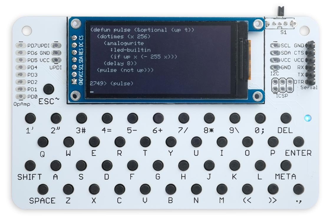
The Lisp Badge LE, a low-power computer programmed in Lisp
with a self-contained keyboard and display.
It's based on an AVR128DB48 which provides 128K bytes of flash memory, and 16K bytes of RAM. There's an integrated 45-key keyboard optimised for Lisp, using reverse-mounted buttons giving room for large key legends on the PCB.
It has a low-power monochrome display, readable in daylight without a backlight, so it's ideal for programming in the garden or on the beach! This gives 10 lines of 41 characters, or graphics with a resolution of 250x122 pixels, supported by several graphics commands.
You can use it to run programs that interface to components such as LEDs and push-buttons via the I/O pins, read the analogue inputs, and operate external devices via the I2C and SPI interfaces.
Introduction
A few years ago I designed the Lisp Badge, a self-contained computer with its own display and keyboard, based on an ATmega1284, that you could program in Lisp. Since then I've been thinking about how I could improve it, and made a list of features I'd like to add.
On the one hand I wanted it to have a better keyboard, and be low power, powered from a button cell, with an eInk display that you could see in daylight. On the other hand I wanted it to have a colour TFT graphics display, and use a fast 32-bit ARM processor, with support for floating-point arithmetic.
I soon realised that these requirements are incompatible in a single design, and so set about designing two different Lisp Badges to meet the two sets of requirements. This Lisp Badge LE (low energy) is the first of those designs, and has the following new features:
Processor and memory
It’s based on an AVR128DB48 (or AVR128DA48) running at 24MHz, and provides 2800 Lisp objects, about the same as the original Lisp Badge. You can save the entire workspace to flash.
Current consumption
The Lisp Badge LE draws only 6mA from its CR2032 button cell, and so should have a life of about 40 hours. There’s a physical on/off switch too for long periods of inactivity.
Lisp language
The Lisp Badge LE runs the AVR version of uLisp which provides 16-bit integer arithmetic, arbitrary length symbols and strings, lists, multi-dimensional arrays, Arduino interface functions, debugging features, and built-in documentation.
Display
The display is a low-power monochrome graphics display [1] which I explored in an earlier article; see Monochrome Low-Power Display Library. It has a resolution of 250x122 pixels, and a text resolution of 10 lines of 41 characters per line. It supports reading back from the display, which makes it possible to support a full range of graphics functions, including plotting points, drawing lines, drawing outline and filled rectangles circles or triangles, and plotting characters and text at normal size or enlarged by any integer scale factor.
Keyboard
The keyboard takes advantage of push buttons that mount on the reverse of the board, with the button caps protruding through holes in the PCB. This makes it much easier to use than on the original Lisp Badge because it's easier to press the keys, and there's space for larger key legends. The push buttons are available from Adafruit [2]. or The Pi Hut in the UK [3].
It uses the same 45-key layout as the original Lisp badge, with upper and lower-case characters, digits, and the symbols required by uLisp. However, it now provides an addition META modifier key in addition to SHIFT, allowing you to enter characters that don't have a dedicated key on the keyboard.
Peripherals
There’s a large piezo speaker that supports playing notes, and a reverse-mounting LED that shines through a hole on the front of the board.
Here's the full specification:
Lisp Badge – Specification
Size: 107mm x 67mm (4.20" x 2.65").
Display: 41 characters x 10 lines, or 250 x 122 pixels.
Keyboard: Integrated 45-key keyboard providing upper and lower-case characters, digits, and the symbols required by uLisp.
The META key pressed in conjunction with another key gives access to the following characters not available from the main keyboard:
| META + | A | C | D | E | P | Q | T | U | V | < | > |
| Character | & | : | $ | ! | % | ? | @ | ^ | | | { | } |
Memory available: 2800 Lisp cells (11200 bytes).
Flash: 16384 bytes of flash are reserved for use to save the Lisp workspace using save-image.
Processor: AVR128DB48
Clock speed: 24 MHz.
Current consumption: Approx. 6 mA. A CR2032 cell has a typical capacity of 225 mAh, so this should give a life of about 40 hours.
Types supported: list, symbol, integer, character, string, stream, and array.
An integer is a sequence of digits, optionally prefixed with "+" or "-". Integers can be between -32768 and 32767. You can enter numbers in hexadecimal, octal, or binary with the notations #x2A, #o52, or #b101010, all of which represent 42.
User-defined symbol names can have arbitrary names. Any sequence that isn't an integer can be used as a symbol; so, for example, 12a is a valid symbol.
There is one namespace for functions and variables; in other words, you cannot use the same name for a function and a variable.
Includes a mark and sweep garbage collector. Garbage collection takes 5 msec.
Language
uLisp, a subset of Common Lisp, with the following 196 Lisp functions and special forms:
* + - / /= 1+ 1- < <= = > >= ? abs analogread analogreadresolution analogreference analogwrite and append apply apropos apropos-list aref array-dimensions arrayp ash assoc atom bit boundp break caaar caadr caar cadar caddr cadr car case cdaar cdadr cdar cddar cdddr cddr cdr char char-code characterp check-key closure cls code-char concatenate cond cons consp dacreference decf defcode defun defvar delay digitalread digitalwrite documentation dolist dotimes draw-char draw-circle draw-line draw-pixel draw-rect draw-triangle edit eq equal error eval evenp fill-circle fill-rect fill-screen fill-triangle first for-millis format funcall gc get-pixel globals glyph-pixel if ignore-errors incf integerp keyboard keywordp lambda length let let* list list-library listp load-image locals logand logbitp logior lognot logxor loop make-array makunbound mapc mapcan mapcar max member millis min minusp mod not note nothing nth null numberp oddp or pinmode plot plot3d plusp pop pprint pprintall prin1 prin1-to-string princ princ-to-string print progn push quote random read read-byte read-from-string read-line register require rest restart-i2c return reverse room save-image search second set set-cursor setf setq sleep sort streamp string string< string= string> stringp subseq symbolp t terpri third time trace truncate unless untrace unwind-protect when with-i2c with-output-to-string with-sd-card with-serial with-spi write-byte write-line write-string zerop
It also provides 37 keywords such as :input, :output, and :led-builtin, as a convenient way of entering Arduino constants.
For a full definition see uLisp Language Reference.
Graphics extensions
The Lisp Badge LE includes a graphics library to allow you to do plotting on the display; for details see Graphics extensions. These work using a coordinate system with the origin at top left:
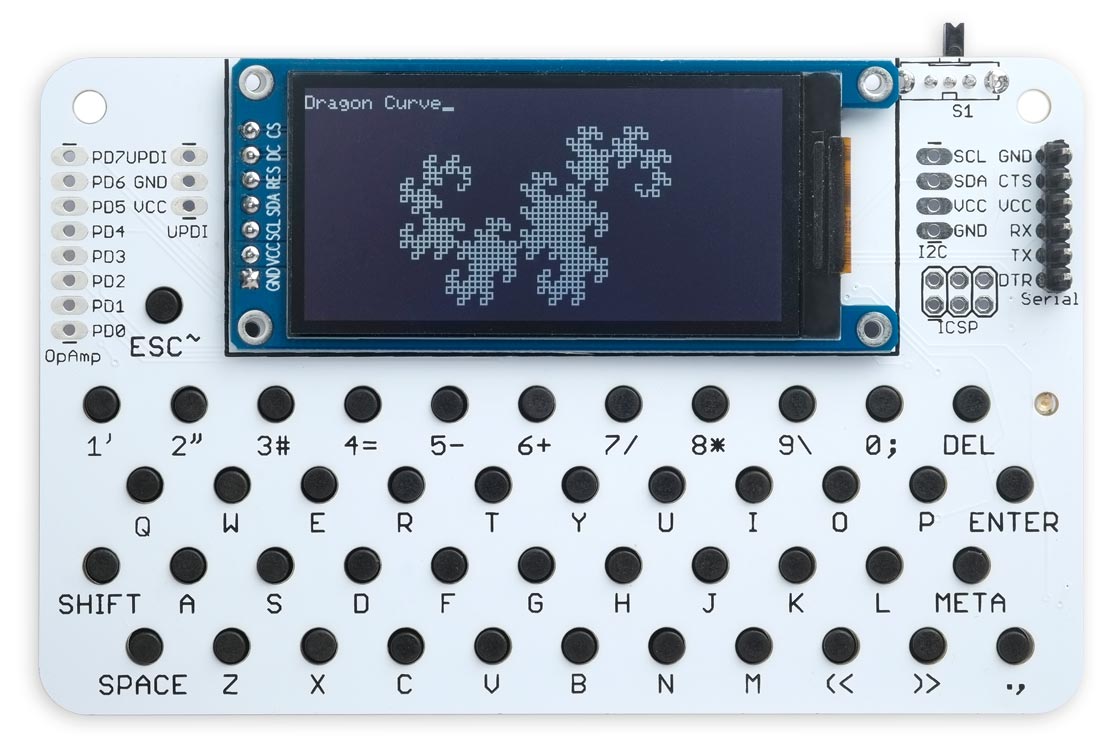
A fractal Dragon Curve drawn in Lisp on the Lisp Badge LE using the graphics extensions.
Assembler
The Lisp Badge LE also includes an AVR assembler which allows you to generate and run machine-code functions, written in AVR mnemonics, using an assembler written in Lisp. For details see AVR assembler overview.
The language includes several extensions specifically for the Lisp Badge, including plot and plot3d, for plotting graphs and 3d functions, and keyboard and check-key for reading the keyboard in real time. For details see Lisp Badge LE extensions.
Interfaces
These interfaces are brought to headers at the edge of the Lisp Badge LE board. The numbers in brackets refer to Arduino pin numbers:
- Eight analogue input pins using analogread: PD0 to PD7 (22 to 29).
- VCC, GND, and UPDI.
- Two analogue outputs using analogwrite: MOSI0 (4) and MISO0 (5).
- Digital input and output using pinmode, digitalread, and digitalwrite: TX0 (0), RX0 (1), SCL0 (2), SDA0 (3), MOSI0 (4), MISO0 (5), SCK0 (6), and PD0 to PD7 (22 to 29)
- I2C interface using with-i2c and restart-i2c: SCL0 (2) and SDA0 (3), plus VCC and GND.
- SPI interface using with-spi: MOSI0 (4), MISO0 (5), and SCK0 (6), plus VCC and GND.
- Serial interface (FTDI) using with-serial: TX0 (0) and RX0 (1), plus DTR, VCC, and GND.
Analogue output PB4 (12) is connected to a piezo speaker, which can use analogwrite or note.
The SHIFT (33) and META (11) keys can be used as digital inputs, read with digitalread and referenced as :shift-key and :meta-key.
PA7 (7) is connected to an LED on the front panel, referenced as :led-builtin. You can turn it on and off with digitalwrite, or vary its brightness with analogwrite.
Entering programs
You can enter commands and programs by typing them at the keyboard, and pressing ENTER. A keyboard buffer is provided that buffers a full screen of text, and you can use the DEL key to delete characters and correct typing mistakes. The line editor includes parenthesis matching which automatically highlights matching brackets in inverse video as you type in a program. This makes it much easier to enter a program correctly, and is especially helpful in telling you how many closing brackets to type at the end of defining a function.
For example, the following program pulsates the built-in LED slowly on and off:
(defun pulse (&optional (up t))
  (dotimes (x 256)
    (analogwrite :led-builtin (if up x (- 255 x)))
    (delay 8))
  (pulse (not up)))
It's shown nicely formatted here for clarity, but you can type it in as one continuous line, only pressing ENTER at the end. To run the program type:
(pulse)
Connecting to a computer
You can connect the Lisp Badge to a computer by plugging a 3.3V FTDI USB-to-serial converter onto the FTDI connector on the top right of the Lisp Badge, and then connecting this to the computer using a USB cable. You can then use the Serial Monitor in the Arduino IDE to enter and edit programs as described in Using uLisp.
I used the 3.3V FTDI Basic Breakout from Sparkfun [4]. When using it with the Lisp Badge it powers the Lisp Badge, and so the battery should be left switched off.
The circuit
Here's the main part of the circuit:
Circuit of the Lisp Badge, based on an AVR128DB48 microcontroller.
The keyboard arranges the keys in a matrix of four rows and 11 columns:
The circuit of the Lisp Badge keyboard matrix.
► Parts list
Construction
I created a PCB in Eagle, and ordered a set of boards from PCBWay. I chose white PCBs to contrast with the black buttons. The board is the same width as the original Lisp Badge, but slightly taller to accomodate the larger display.
After a bit of experimentation I chose a board thickness of 1.2mm. With the standard 1.6mm thick PCB material the reverse-mounted buttons didn't protrude far enough through the holes, and 0.8mm made the boards too bendy, but 1.2mm was ideal.
The components, apart from the display, are mounted on the back of the board:
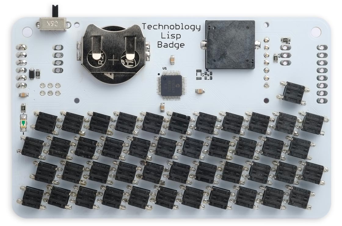
The reverse side of the Lisp Badge printed circuit board.
The push buttons are mounted at a 15° angle, which makes it possible to pack them closer together. I've taken advantage of the fact that the terminals on each side of the push buttons are connected together to link the rows and columns of the key matrix across the board, and simplify the PCB track layout. A consequence of this is that if one push button is omitted, or has a faulty connection, all the other buttons to its left or below it across the keyboard may not work. Understanding this should help you track down any faulty soldering.
The PCB uses 0805 resistors and capacitors. The LED is a reverse-mounting 1206 LED [5] to make the front of the board flush.
The board will accommodate either a 16 x 16mm SMD piezo speaker [6], or a 11 x 9mm SMD piezo speaker [7].
The battery holder is an SMD 20mm coin cell holder available from Sparkfun [8], or from Proto-PIC in the UK [9]. Note that on many button cells the negative terminal is concave, and doesn't make good contact with the pad on the PCB. I therefore recommend melting some solder on the circular PCB contact to provide extra thickness before mounting the battery holder.
The display is held in place with a double-sided self-adhesive foam pad, and then soldered to the board with the seven header pins. There are also four mounting holes if you prefer to use screw mounting. I recommend leaving the display uninstalled until you have tested the rest of the board, because it's likely to be sensitive to overheating.
I used a Youyue 858D+ hot air gun at 275°C to solder the small SMD components and push buttons, and then used a conventional soldering iron for the display, battery holder, switch, piezo speaker, and connectors.
The PCB has space for a 5 x 3.2mm 32.768kHz crystal and its capacitors which you could use with the RTC peripheral to provide accurate timekeeping. However, I didn't fit it on the prototype as the internal clock is already pretty accurate.
The program
The Lisp Badge program is based on the code for the AVR version of uLisp Version 4.4 (see Download uLisp), with the addition of routines to handle the display and keyboard, and the plot extensions.
Display
The display routine is based on the routine I developed for the display in my project Monochrome Low-Power Display Library. The display driver is the ST7302 [10], and it shares some similarities with the ST7735 used for colour TFT displays. Here's the display layout:
The display is divided into 11 lines, each of which is 12 pixels high, and 125 columns, each of which is 2 pixels wide. Note that because 122 isn't an exact multiple of 12, only part of the last line actually appears on the display.
Unlike on the colour TFT displays each pixel isn't individually addressable; in fact, the minimum update is to write three bytes to the display, which defines the state of a block of 2x12 pixels corresponding to one column and one row. Fortunately the display supports reading back the display memory, so it's not necessary to maintain a copy of the display in RAM to do things like line drawing; instead, to set a single pixel we can read the 2x12 block, change one pixel, and write it back.
Reading from the display
The routine ReadBlock() reads a 12x2 pixel block from the display memory specified by the column, from 0 to 124, and the line, from 0 to 10:
uint32_t ReadBlock (uint8_t column, uint8_t line) {
  uint32_t pix = 0;
  PORT_TOGGLE(1<<cs);
  Command2(CASET, 25+line, 25+line);
  Command2(RASET, column, column);
  Command(RAMRD);
  PORT_INPUT(1<<mosi);                     // mosi input
  for (uint8_t i=0; i<25; i++) {
    PORT_TOGGLE(1<<sck);
    pix = pix<<1 | (PORT_IN>>mosi & 1);
    PORT_TOGGLE(1<<sck);
  }
  PORT_OUTPUT(1<<mosi);                    // mosi output
  PORT_TOGGLE(1<<cs);
  return pix;
}
When reading from display memory you have to do a dummy read, which is why the main loop is executed 25 times rather than 24 times.
The companion routine PlotBlock() writes back a 12x2 pixel block to the display memory:
void PlotBlock (uint32_t block, uint8_t column, uint8_t line) {
  PORT_TOGGLE(1<<cs);
  Command2(CASET, 25+line, 25+line);
  Command2(RASET, column, column);
  Command(RAMWR); Data(block>>16); Data(block>>8); Data(block);
  PORT_TOGGLE(1<<cs);
}
Scrolling
The display doesn't provide hardware scrolling in the vertical direction, so scrolling is done in software by calling ScrollDisplay(), which uses the ReadBlock() and PlotBlock() routines:
void ScrollDisplay () {
  uint32_t block, block2;
  for (uint8_t x = 0; x < Columns*3; x++) {
    block = ReadBlock(x, 0);
    for (uint8_t y = 1; y < Lines; y++) {
      block2 = ReadBlock(x, y);
      if (block2 != block) {                   // Optimisation if already the same
        PlotBlock(block2, x, y-1);
        block = block2;
      }
    }
  }
  ClearLine(LastLine);
}
The routine optimises the scrolling by only writing blocks when necessary if they have been changed by the scrolling.
Keyboard
The keyboard uses the AVR128DB48's Timer/Counter TCB3 to generate an interrupt at about 250Hz. Each call of the interrupt service routine takes the next column low in the keyboard matrix, and it then tests to see if any of the four row inputs has been pulled low by the pressing of a push button. If so, the button's position is looked up in the key table Keymap[] to translate it to the ASCII code of the key. This also takes into account the state of the SHIFT and META keys, which are connected to dedicated inputs.
A keyboard buffer buffers a full screen of text, so you can use the DEL key to delete characters and correct typing mistakes. The line editor includes parenthesis matching which automatically highlights matching brackets in inverse video as you type in a program.
Installing a bootloader
To program the Lisp Badge I recommend using Spence Konde's DxCore on GitHub.
The first step is to install a bootloader using a UPDI programmer. Because the display is only tolerant of 3.3V you should power the Lisp Badge from 3.3V while programming, or do the programming before connecting the display to the board.
The recommended option is to use a USB to Serial board, such as the SparkFun FTDI Basic board [11], connected with a 4.7kΩ resistor as follows:
Choose the AVR DB-series (Optiboot) option under the DxCore heading on the Board option on the Tools menu. Check that the subsequent options are set as follows (leave other options at their defaults):
Chip: "AVR128DB48"
Clock Speed: "24MHz internal"
Bootloader Serial Port (Bootloader burn req'd): "USART0 (default pins): TX PA0, RX PA1"
Set the Programmer option as appropriate for the UPDI programmer you are using. Then choose Burn Bootloader.
Uploading the Lisp Badge code
The next step is to install the Lisp Badge code via the serial connection, using the bootloader you have just installed. Plug a 3.3V FTDI USB-to-serial converter into the FTDI connector on the PCB. I used the same SparkFun FTDI Basic Breakout [12].
Leave the DxCore options set as described above, and choose the USB port from the Port submenu. Then choose Upload from the Sketch menu to upload uLisp.
Note that this stage will fail if you didn't set the Bootloader Serial Port correctly in the previous step, and you'll need to go back and repeat that step with the correct setting.
You should then be able to choose Serial Monitor from the Tools menu in the Arduino IDE, and type Lisp commands at the uLisp prompt.
Resources
Get the latest Lisp Badge LE source from GitHub, together with the Eagle files for the PCB so you can make yourself a board, at: Lisp Badge LE.
Or order a printed circuit board from PCBWay here: Lisp Badge LE.
Update
27th February 2024: Corrected a couple of mistakes in the parts list.
- ^ 2.13" 122*250 E-paper ink screen TFT Module on AliExpress.
- ^ Reverse Mount Tactile Switch Buttons on Adafruit.
- ^ Reverse Mount Tactile Switch Buttons on The Pi Hut.
- ^ FTDI Basic Breakout 3.3V on Sparkfun.
- ^ Kingbright KPTL-3216QBC on Farnell.com.
- ^ Square Wave External Piezo Buzzer on RS Online.
- ^ KMTG1102-A1 Piezo Buzzer on RS Online.
- ^ Coin Cell Battery Holder - 20mm (SMD) on SparkFun.
- ^ Coin Cell Battery Holder - 20mm (SMD) on Proto-PIC.
- ^ ST7302 Datasheet download from GitHub.
- ^ SparkFun FTDI Basic Breakout - 3.3V on SparkFun.
- ^ SparkFun FTDI Basic Breakout - 3.3V on SparkFun.
blog comments powered by Disqus