Minimal ATmega4809 on a Breadboard
26th February 2020
This article shows how you can build a minimal microcontroller on a breadboard based on the ATmega4809, the microprocessor used in the latest AVR-based Arduino boards:
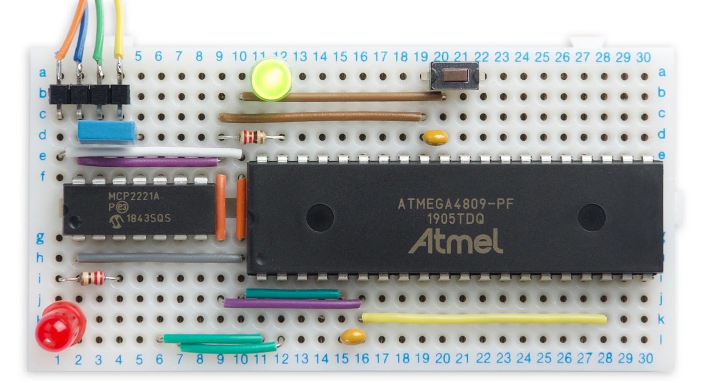
Minimal ATmega4809-based microcontroller using an MCP2221A USB-to-serial converter.
It includes a USB-to-serial converter so you can connect it to your computer's USB port and program it from the Arduino IDE.
Introduction
Arduino's successors to their classic Arduino Uno board are the Arduino Nano Every [1] and the Arduino Uno WiFi Rev2 [2]. These are based on the ATmega4809 [3], one of Microchip's AVR processors from their new 0-series ATmega range. As well as having more program memory and RAM than the Arduino Uno's ATmega328P, the ATmega4809 has some interesting new features, including a 20MHz clock, an event system, and configurable custom logic.
One of the attractions of the old ATmega328P was that it was available in a DIP package, making it ideal for prototyping. Microchip's latest range of AVR processors aren't available in DIP packages, with one exception: the ATmega4809 [4]. Coupled with their MCP2221 USB-to-serial chip, which is also available in a DIP package [5], you can make a complete microcontroller on a breadboard that connects straight to a USB port, and can be programmed from the Arduino IDE just like other Arduino boards.
The circuit
Although you can program an ATmega4809 chip directly, via UPDI, for developing programs it's much more convenient to install a bootloader, and then program via the serial interface. This has the added benefit that you can use the Arduino Serial Monitor for reading input and printing out values while debugging.
I describe two alternatives here; using an FTDI USB-to-serial converter board, and using an MCP2221A USB-to-serial chip.
Using an FTDI USB-to-serial converter
Here's the option of using an FTDI USB-to-serial converter board:
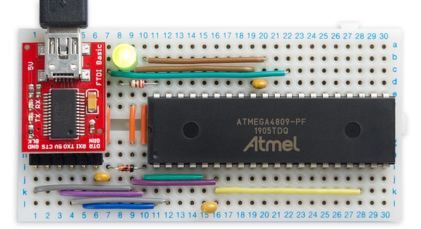
Minimal ATmega4809-based microcontroller using an FTDI USB-to-serial converter board.
There are several alternative USB-to-serial converter boards; the one I used is the FTDI Basic Breakout from Sparkfun [6], available from HobbyTronics in the UK [7].
Here's the circuit for using the FTDI USB-to-serial board:
Circuit of the ATmega4809-based microcontroller using an FTDI USB-to-serial converter board.
I've also connected an LED to PA7 (Arduino pin 7) which is defined as the built-in LED flashed by the Blink example program.
Building your own USB-to-serial converter
A lower cost alternative to buying an FTDI breakout is to build your own circuit. Fortunately there's a prototyping-board friendly USB-to-serial converter available in a PDIP package from Microchip: the MCP2221A [8]. You can connect a USB port directly to it with no other components. This version is shown in the photograph at the start of the article.
Here's the circuit for using the MCP2221A:
Circuit of the ATmega4809-based microcontroller using an MCP2221A USB-to-serial converter.
I made a USB cable using a length of four-core ribbon cable and a USB DIY Connector Shell [9], with a four-pin header at the other end to plug into the prototyping board.
One limitation of the MCP2221A is that it doesn't provide the DTR handshaking signal that is usually used to reset the microcontroller chip and start the bootloader receiving data. Fortunately there's a simple solution: as shown in the above circuit you can provide a Tx LED that lights up as soon as the USB-to-serial converter starts transmitting. When the Tx LED flashes give a brief press on the Reset button; the upload will then start, and the Tx LED will stay lit continuously until the upload is finished.
As in the other circuit I've again connected an LED to PA7 (Arduino pin 7) which is defined as the builtin LED flashed by the Blink example program.
Installing a bootloader
The first step is to install a bootloader on the ATmega4809 chip so you can subsequently upload programs from the Arduino IDE via the serial port, and use the serial monitor for debugging.
The Arduino megaAVR Boards core provided for the ATmega4809-based Arduino boards isn't suitable, because it assumes that the serial port is on TXD3 (PB0) and RXD3 (PB1), which aren't available on the 40-pin ATmega4809.
Fortunately GitHub user MCUdude has developed a superb core for all the new ATmega 0-series chips, called MegaCoreX core, and this allows you to install a bootloader for use with any serial port. I chose Serial1 (TDX1 and RXD1) as they were conveniently placed on the breadboard. For details of the MegaCoreX pinouts for the 40-pin PDIP package see: MegaCoreX DIP-40 Standard Pinout.
First install MegaCoreX core from GitHub: see Installing MegaCoreX.
Then, in the Arduino IDE:
Choose the ATmega4809 option under the MegaCoreX heading on the Board menu.
Check that the subsequent options are set as follows (ignore any other options):
Bootloader: "Optiboot (UART1 default pins)"
Clock: "Internal 16 MHz"
Pinout: "40/48 pin standard"
Reset pin: "Reset"
Programmer: "jtag2updi (megaTinyCore)"
Connect a UPDI programmer to the UPDI pin, VCC, and GND. I used my UPDI Programmer Stick; alternatively you can make a UPDI programmer from an Arduino Uno, or other ATmega328P-based board, as described in Make UPDI Programmer.
Select the UPDI programmer from the Port menu.
Then choose Burn Bootloader from the Tools menu to upload the bootloader to the ATmega4809.
Uploading a program
Now you've installed a bootloader you should be able to upload a program to the ATmega4809 via the serial port. For example, you could use the Blink demo program.
In the Arduino IDE:
Choose the ATmega4809 option under the MegaCoreX heading on the Board menu.
As before, check that the subsequent options are set as follows (ignore any other options):
Bootloader: "Optiboot (UART1 default pins)"
Clock: "Internal 16 MHz"
Pinout: "40/48 pin standard"
Reset pin: "Reset"
This time the Programmer option is irrelevant.
Connect the Minimal ATmega4809 board to your computer's USB port, and select it from the Port menu.
Click Upload to upload the Arduino sketch to the ATmega4809. If you're using the MCP2111A version briefly press the Reset button when the Tx LED flashes.
Your program should then be running.
Using serial
Because of the reduced number of pins on the DIP version of the ATmega4809, if you want to use the Arduino Serial Monitor with it you need to use Serial1 rather than Serial.
Try installing uLisp
You might like to try installing my Lisp interpreter, uLisp:
Download the AVR version of uLisp from Download uLisp.
You need to make one change to the uLisp source to reflect the fact that the Minimal ATmega4809 board uses Serial1 rather than Serial3:
Search for the line:
#define Serial Serial3
and change it to:
#define Serial Serial1
Then click Upload to upload uLisp to the ATmega4809.
Once installed, you should be able to type or copy-and paste Lisp programs into the field at the top of the Serial Monitor window, and click the Send button or press Return to enter them.
For examples of using uLisp see the uLisp site. Most of the Simple examples will run on the ATmega4809 uLisp.
For help with using uLisp visit the uLisp Forum.
Other points
Minimising power consumption
The DIP version of the ATmega4809 is based on the same die as the standard 48-pin ATmega4809, supplied in QFN or QFP packages. As a result, there are 8 I/O pins that aren't accessible.
To minimise power consumption due to leaving unconnected pins as inputs Microchip recommend these pins PB0 to PB5 and PC6 to PC7 should either be disabled with INPUT_DISABLE, or left enabled with pull-ups using PULLUPEN. Here's how to disable the pins:
  PORTB.PIN5CTRL = PORT_ISC_INPUT_DISABLE_gc;
  PORTB.PIN4CTRL = PORT_ISC_INPUT_DISABLE_gc;
  PORTB.PIN3CTRL = PORT_ISC_INPUT_DISABLE_gc;
  PORTB.PIN2CTRL = PORT_ISC_INPUT_DISABLE_gc;
  PORTB.PIN1CTRL = PORT_ISC_INPUT_DISABLE_gc;
  PORTB.PIN0CTRL = PORT_ISC_INPUT_DISABLE_gc;
  PORTC.PIN7CTRL = PORT_ISC_INPUT_DISABLE_gc;
  PORTC.PIN6CTRL = PORT_ISC_INPUT_DISABLE_gc;
In practice I couldn't detect any difference in current consumption.
Experimenting with custom logic
One new feature in the ATmega4809 is CCL (Configurable Custom Logic), which allows you to connect the I/O pins via simple logic gates. For example, you could configure the CCL to generate an interrupt when a particular bit pattern is present on four inputs.
MCUdude has included a library in MegaCoreX for interfacing with the CCL; see MegaCoreX Logic.
Update
27th February 2020: Added decoupling capacitors to the circuit diagrams.
11th July 2020: Added a note about using Serial1 instead of Serial.
- ^ Arduino Nano Every on Arduino Store.
- ^ Arduino WiFi Rev2 on Arduino Store.
- ^ ATmega4808/4809 Datasheet on Microchip.
- ^ ATmega4809, 40 pins, DIP on Farnell.
- ^ MCP2221A, 14 pins, DIP on Farnell.
- ^ FTDI Basic Breakout on Sparkfun.
- ^ FTDI Basic Breakout on HobbyTronics.
- ^ MCP2221A datasheet on Microchip.
- ^ USB DIY Connector Shell on Adafruit.
blog comments powered by Disqus