Graphical Analogue Clock
11th October 2022
This is an analogue clock that displays the time on a colour TFT graphics display:
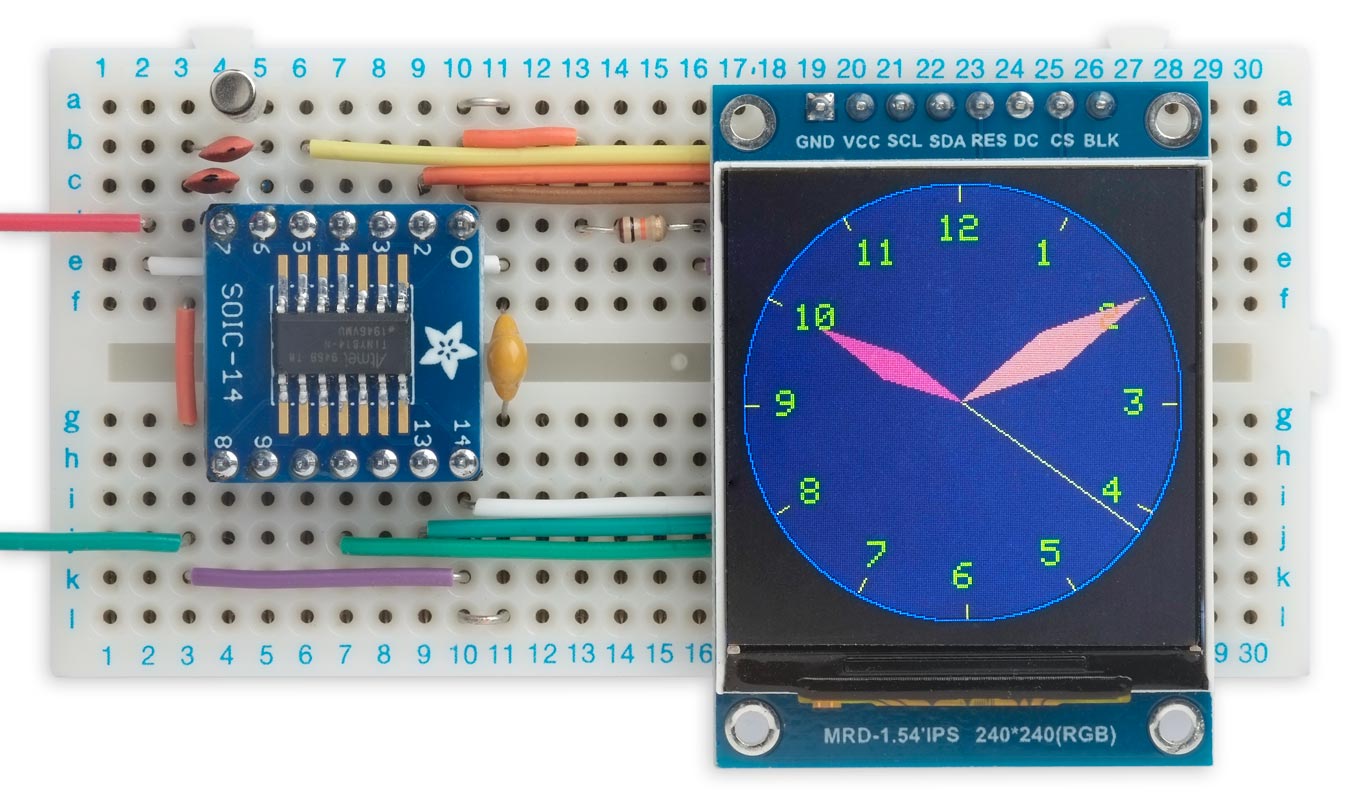
Analogue clock, based on an ATtiny814, displays the time on a 240x240 colour TFT display.
It's based on an RGB TFT display controlled by an ATtiny814. It uses a crystal-controlled oscillator to keep accurate time, and takes advantage of the routines for reading from a TFT display described in my earlier article Reading from a TFT Display.
I give the circuit so you can build the project on a prototyping board. Alternatively you can use my Universal TFT Display Backpack.
Introduction
This started as a demo program for my TFT Graphics Library with support for reading from the display, but it grew in complexity, so I decided to write it up as a stand-alone project.
How it works
Without the ability to read back from the display you would have to redraw the whole display every time the hands move, which will be once a second if the clock has a seconds hand. This would require a fast processor.
This clock avoids the need to do this by using the ability to read from the TFT display to exclusive-OR the colour of each hand onto the image of the clock face. When the hand moves, you can remove it from its last position by drawing it again, which will restore the background to its previous state. This ensures that features under the hands, such as the hour numbers, aren't wiped out when the hands pass over them.
Suitable displays
The clock is designed to work with a 240x240 or 320x240 RGB TFT display available from AliExpress. I've also made a lower-resolution version that will work on a 128x128 or 160x128 display; see Lower resolution version. The following displays are suitable:
| Manufacturer | Size | Width | Height | Voltage | Driver | Link |
| AliExpress | 1.54" | 240 | 240 | 3.3V | ST7789 | 1.54" TFT 240x240 LCD Display * |
| AliExpress | 2.0" | 320 | 240 | 3.3V | ST7789V | 2.0" TFT 240x320 LCD Display |
| AliExpress | 1.44" | 128 | 128 | 3.3V | ST7735S | 1.44" 128x128 SPI TFT display * |
| AliExpress | 1.8" | 160 | 128 | 3.3V | ST7735 | 1.8" 128x160 SPI TFT display * |
* Compatible with my Universal Display Backpack.
Unfortunately Adafruit displays aren't compatible with this application, because they don't support reading from the display; there's more information about this in my article Reading from a TFT Display.
The circuit
Here's the circuit, which is essentially the circuit of the backpack:
Circuit of the Graphical Analogue Clock, based on an ATtiny814.
The program occupies 5Kbytes so you need an ATtiny 1-series device with at least 8Kbytes, such as the ATtiny814 up to an ATtiny3214. The 0-series devices aren't suitable as they don't support an external crystal. You should also be able to use one of the newer 2-series devices, but I haven't tried it.
The clock uses the ATtiny814 Real-Time Clock to generate an interrupt every second, with the timing controlled by a 32.768kHz crystal. For the crystal I used a low-cost cylindrical clock crystal [1] which typically has a load capacitance of 12.5pF. To calculate the capacitor values use the formula C = 2(CL - CS), where CL is the load capacitance, and CS is the stray capacitance which is usually estimated to be 2.5pF on a PCB. This gives C=20pF.
If you've built the circuit on a breadboard you can probably omit the capacitors as there will probably be plenty of capacitance between the rows on the breadboard.
Universal TFT Display Backpack
You can also run the program on my Universal TFT Display Backpack with an ATtiny814:
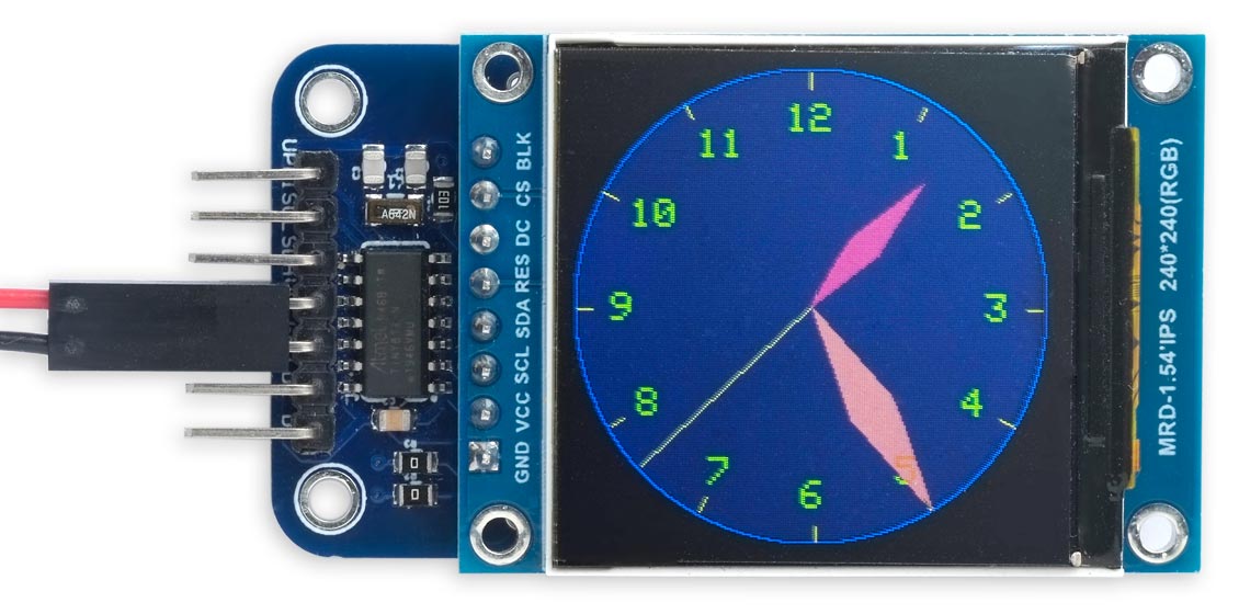
Graphical Analogue Clock running on my Universal TFT Display Backpack.
The program
The program incorporates my library from Reading from a TFT Display.
Drawing the clock background
The routine ClockFace() draws the clock face and hour numbers, but without the hands:
void ClockFace () {
  int x0 = 120, y0 = 120, radius = 120;
  MoveTo(x0, y0); fore = BLUE; DrawCircle(radius);
  radius = radius - 2; fore = DARKBLUE; FillCircle(radius);
  int x = 0, y = 118<<sca;
  for (int i=0; i<60; i++) {
    // Hours and hour marks
    if (i%5 == 0) {
      fore = YELLOW;
      MoveTo(x0+(x>>sca), y0+(y>>sca));
      DrawTo(x0 + ((x*15)>>(sca+4)), y0 + ((y*15)>>(sca+4)));
      scale = 2;
      MoveTo(x0 + ((x>>sca)*13/16) - 3*(1+(i==0))*2, y0 + ((y>>sca)*13/16) - 8);
      fore = GREEN; back = DARKBLUE;
      if (i==0) PlotInt(12); else PlotInt(i/5);
      scale = 1;
    }
    for (int i=2;i--;) { x = x + (y*top)/bot; y = y - (x*top)/bot; }
  }
}
It uses the Minsky circle algorithm to calculate the 60 points around the circle, without needing floating point or trig functions. The value top/bot or 10/191 is a close approximation to (2*π)/120, where 2*π is the number of radians in a circle. 120 is the number of subdivisions of the circle I use, where two subdivisions corresponds to one second. The value sca is a scale factor chosen so that 2sca*118*top fits in an int.
Setting up the real-time clock
The timekeeping uses the RTC peripheral in the ATtiny814, clocked from an external 32.768kHz crystal to give an interrupt every second.
The routine RTCSetup() configures the crystal oscillator, and then specifies this as the clock source for the Real-Time Clock peripheral:
void RTCSetup () {
  uint8_t temp;
  // Initialize 32.768kHz Oscillator:

  // Disable oscillator:
  temp = CLKCTRL.XOSC32KCTRLA & ~CLKCTRL_ENABLE_bm;

  // Enable writing to protected register
  CPU_CCP = CCP_IOREG_gc;
  CLKCTRL.XOSC32KCTRLA = temp;

  while (CLKCTRL.MCLKSTATUS & CLKCTRL_XOSC32KS_bm);   // Wait until XOSC32KS is 0
  temp = CLKCTRL.XOSC32KCTRLA & ~CLKCTRL_SEL_bm;      // Use External Crystal

  // Enable writing to protected register
  CPU_CCP = CCP_IOREG_gc;
  CLKCTRL.XOSC32KCTRLA = temp;
  temp = CLKCTRL.XOSC32KCTRLA | CLKCTRL_ENABLE_bm;    // Enable oscillator

  // Enable writing to protected register
  CPU_CCP = CCP_IOREG_gc;
  CLKCTRL.XOSC32KCTRLA = temp;

  // Initialize RTC
  while (RTC.STATUS > 0);                             // Wait until synchronized

  // 32.768kHz External Crystal Oscillator (XOSC32K)
  RTC.CLKSEL = RTC_CLKSEL_TOSC32K_gc;

  // RTC Clock Cycles 32768, enabled ie 1Hz interrupt
  RTC.PITCTRLA = RTC_PERIOD_CYC32768_gc;
  RTC.PITINTCTRL = RTC_PI_bm;                         // Periodic Interrupt: enabled
}

// Interrupt Service Routine called every second
ISR(RTC_PIT_vect) {
  RTC.PITINTFLAGS = RTC_PI_bm;                        // Clear interrupt flag
  NextSecond(BOTH);
}
It's essentially the same routine as I used in earlier clocks based on ATtiny 1-series chips, such as Mega Tiny Time Watch [Updated].
Moving the hands
The interrupt service routine is called every second:
ISR(RTC_PIT_vect) {
  RTC.PITINTFLAGS = RTC_PI_bm;                        // Clear interrupt flag
  NextSecond(BOTH);
}
It simply calls NextSecond() to advance the hands, if necessary::
void NextSecond (int draw) {
  int x0 = 120, y0 = 120;
  // Positions of hands
  static int secx = 0, secy = 118<<sca;
  static int minx = 0, miny = 118<<sca;
  static int hrx = 0, hry = 86<<sca;
  // Seconds and minutes
  static uint8_t secs = 0, mins = 0;

  // Advance second hand
  fore = White;
  if (draw & UNDRAW) { MoveTo(x0, y0); DrawTo(x0+(secx>>sca), y0+(secy>>sca)); }
  for (int i=2;i--;) { secx = secx + (secy*top)/bot; secy = secy - (secx*top)/bot; }
  if (secs == 59) { secx = 0, secy = 118<<sca; }  // Realign
  if (draw & DRAW) { MoveTo(x0, y0); DrawTo(x0+(secx>>sca), y0+(secy>>sca)); }

  // Advance hour hand every 12 mins
  if (secs == 59 && mins%12 == 0) {
    fore = RED;
    DrawHand(x0, y0, hrx>>sca, hry>>sca);
    for (int i=2;i--;) { hrx = hrx + (hry*top)/bot; hry = hry - (hrx*top)/bot; }
  } else if (secs == 0 && mins%12 == 0) {
    fore = RED;
    DrawHand(x0, y0, hrx>>sca, hry>>sca);
  }

  // Advance minute hand every 60 secs
  if (secs == 59) {
    fore = PINK;
    if (draw & UNDRAW) DrawHand(x0, y0, minx>>sca, miny>>sca);
    for (int i=2;i--;) {minx = minx + (miny*top)/bot; miny = miny - (minx*top)/bot; }
  } else if (secs == 0) {
    fore = PINK;
    if (mins == 0) minx = 0, miny = 118<<sca;  // Realign
    if (draw & DRAW) DrawHand(x0, y0, minx>>sca, miny>>sca);
    mins = (mins + 1)%60;
  }
  secs = (secs + 1)%60;
}
In each case the hand is drawn twice, using exclusive-OR plotting: once in its previous position, to remove the old image, and once in the new position, to draw the new image.
The second hand is draw as a line, and advances every second.
The minute hand advances one second every 60 seconds. Because of the time taken to draw it I undraw the old version and draw the new version on successive calls to NextSecond().
The hour hand advances one second every 12 minutes.
Drawing the hour and minute hands
Both the hour hand and minute hand are drawn by DrawHand() as filled diamond-shaped quadrilaterals, using the routines from Drawing Filled Quadrilaterals and Triangles:
void DrawHand(int x0, int y0, int x, int y) {
   int v = x/2, u = y/2, w = v/5, t = u/5;
   FillQuad(x0, y0, x0+v-t, x0+u+w, x0+x, x0+y, x0+v+t, x0+u-w);
}
Since I only need to plot a filled quadrilateral I've simplified the routine a bit to make it slightly faster.
Setting the time
To set the starting time of the clock you can call SetTime() with the appropriate hour and minute values:
void SetTime (int hour, int minute) {
  uint32_t secs = (uint32_t)(hour * 60 + minute) * 60;
  for (uint32_t i=0; i<secs; i++) NextSecond(NONE);
}
The parameter draw to NextSecond() allows you to specify whether to draw or undraw the hands on each call, and SetTime() calls NextSecond(NONE) to advance the positions of the hands without actually plotting them, which is much faster.
Once the correct time has been set, EnableClock() is called to enable the one-second interrupt:
void EnableClock () {
  RTC.PITCTRLA = RTC.PITCTRLA | RTC_PITEN_bm;
}
Currently you have to specify the start time before you upload the program:
const int Hour = 12, Minute = 34; // E.g. 12:34
Lower-resolution version
I've also provided a lower-resolution version of the clock, with the parameters adapted for a 128x128 colour TFT display:
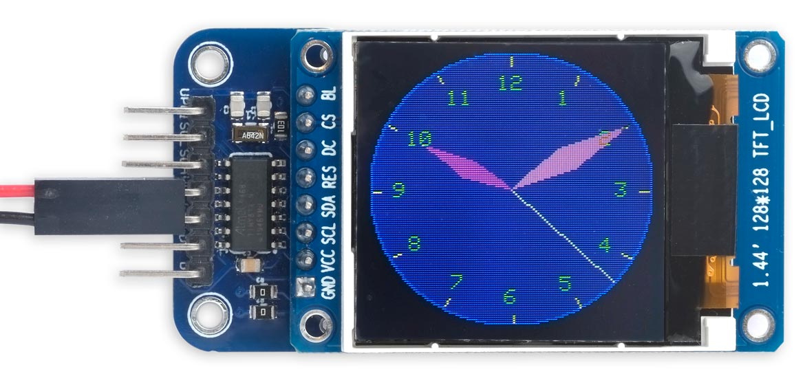
Lower-resolution version of the Graphical Analogue Clock for a 128x128 display.
Compiling the program
Compile the program using Spence Konde's megaTiny Core on GitHub. Choose the ATtiny3224/1624/1614/1604/824/814/804/424/414/404/241/204 option under the megaTinyCore heading on the Board menu. Check that the subsequent options are set as follows (ignore any other options):
Chip: "ATtiny814" (or as appropriate)
Clock: "20 MHz internal"
Then upload the program using a UPDI programmer. The recommended option is to use a 3.3V USB to Serial board, such as the SparkFun FTDI Basic board [2], connected with a 4.7kΩ resistor as follows:
Set the Programmer option to "SerialUPDI with 4.7k resistor or diode (230400 baud)".
Resources
Here's the whole program: Graphical Analogue Clock Program.
And here's the version for a 128x128 (or 160x128) display: Graphical Analogue Clock 128x128.
- ^ 32.768 kHz Crystal on Adafruit.
- ^ SparkFun FTDI Basic Breakout - 3.3V on Sparkfun.
blog comments powered by Disqus