Two-Digit Thermometer
9th April 2019
This is a two-digit LED digital thermometer I made as a birthday present for my friend’s son. As he's only two years old he can’t read yet, but he can read numbers, so I thought it would be fun for him to have something that would tell him the temperature on a seven-segment display:
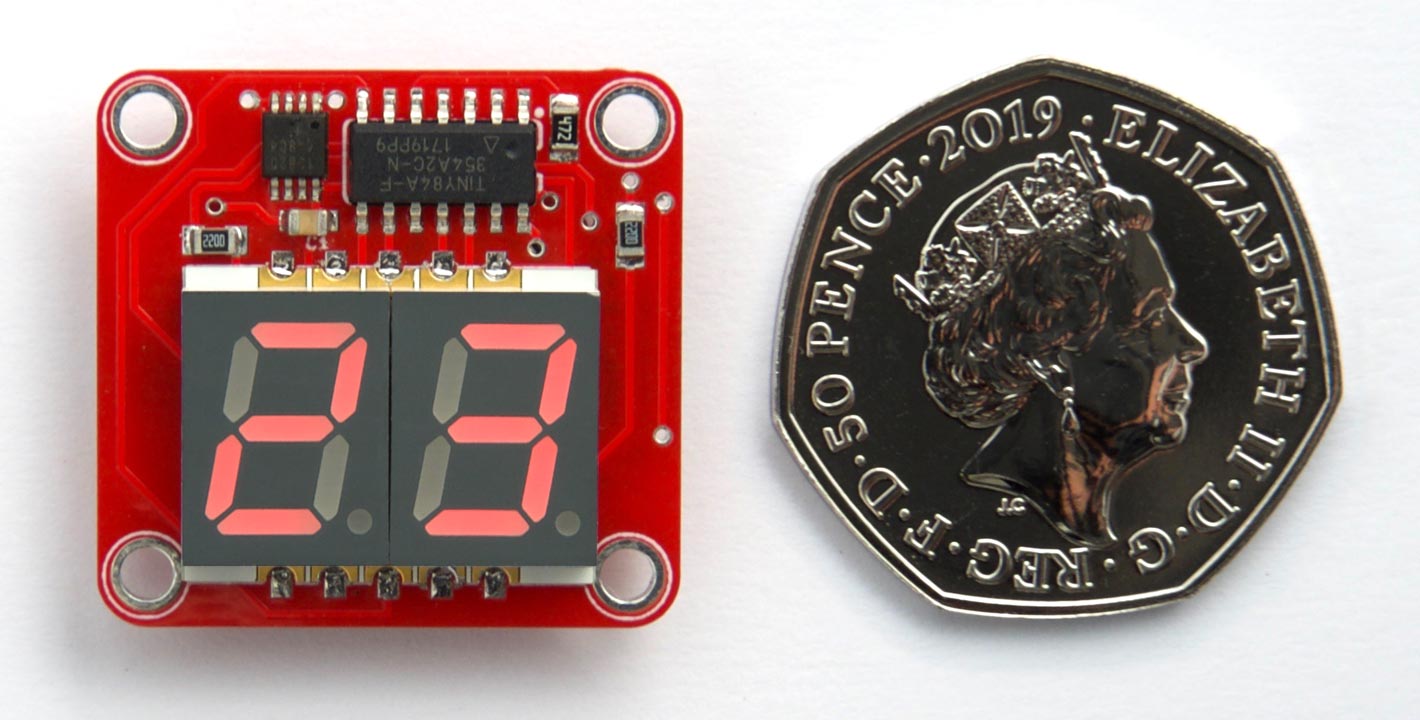
Two-digit thermometer, based on an ATtiny84 and a DS18B20 1-Wire temperature sensor.
It uses a DS18B20 1-Wire temperature sensor, and an ATtiny84 to drive the display and read the sensor. It's just over 25mm square; about the size of a British 50 pence piece.
Introduction
The two-digit thermometer is designed so it could be put in a waterproof case outside the window, to show the outside temperature in all weathers. To conserve power the thermometer flashes the temperature every 24 seconds, and then goes to sleep, and it achieves a battery life of about a year with a CR2032 button cell.
The thermometer can display temperatures between -19°C and 99°C. To display temperatures between -10°C and -19°C the left-hand display is used to display "-1". Outside this range it displays 'Lo' for temperatures below -19°C or 'Hi' for temperatures above 99°C. If you live in a part of the world where temperatures regularly reach below -19°C you could change it to light the decimal points to indicate negative temperatures.
The circuit
Here's the circuit, following the way the prototype was laid out on the breadboard:
Circuit of the Two-Digit Thermometer, based on an ATtiny84 and a DS18B20 temperature sensor.
The ATtiny84 has just enough I/O lines to drive the display and read the one-wire input from the DS18B20 temperature sensor. I used the 8MHz internal clock, as my 1-wire interface was designed to work at 8MHz.
Construction
The prototype
I built a prototype on a mini breadboard, available from SparkFun [1] or HobbyTronics in the UK [2]:
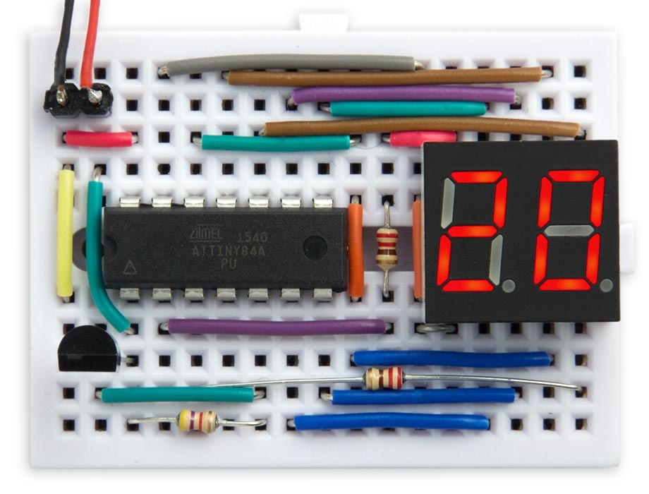
Prototype of the two-digit thermometer, on a mini breadboard.
For the prototype I used a TO-92 DS18B20, and a PDIP ATtiny84. The display was a two-digit seven-segment common-anode 3.6" LED display type 3621AS from AliExpress.
The PCB
For the final version I designed a board in Eagle and sent it to PCBWay for fabrication [3]. There's a link to the Eagle files at the end of the article if you want to make yourself a board.
This used an ATtiny84 in an SOIC package, and a DS18B20 in an 8-pin µSOP package available from RS-Online [4] or AliExpress [5]. The resistors, capacitor, and LED are all 0805 size. I soldered all the SMD components apart from the display using a Youyue 858D+ hot air gun set to 250°C.
The LED display was a two-digit seven-segment common-anode 10mm surface-mount type , and I soldered this with a conventional soldering iron. I built two versions, with red [6] and yellow [7] displays. Here's the yellow one:
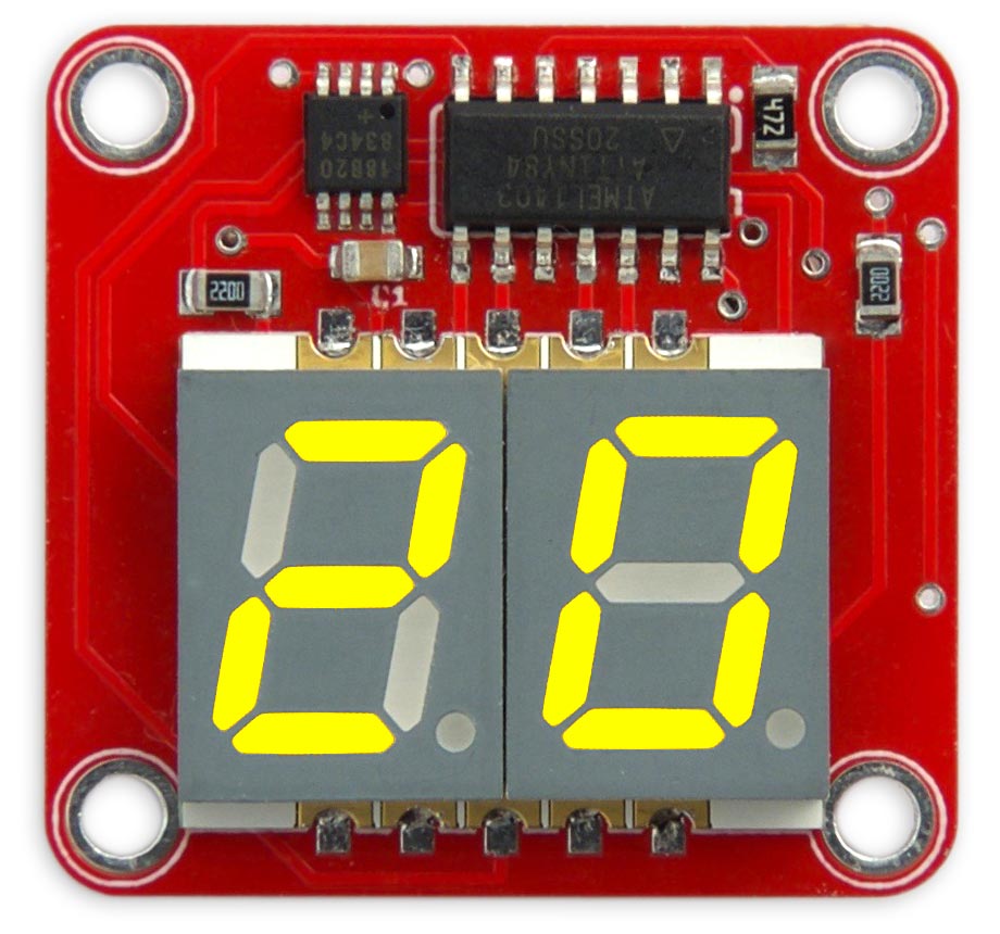
Version of the two-digit thermometer with a yellow LED display.
The battery holder is an SMD 20mm coin cell holder available from Sparkfun [8], or from Proto-PIC in the UK [9], soldered to the back of the board:
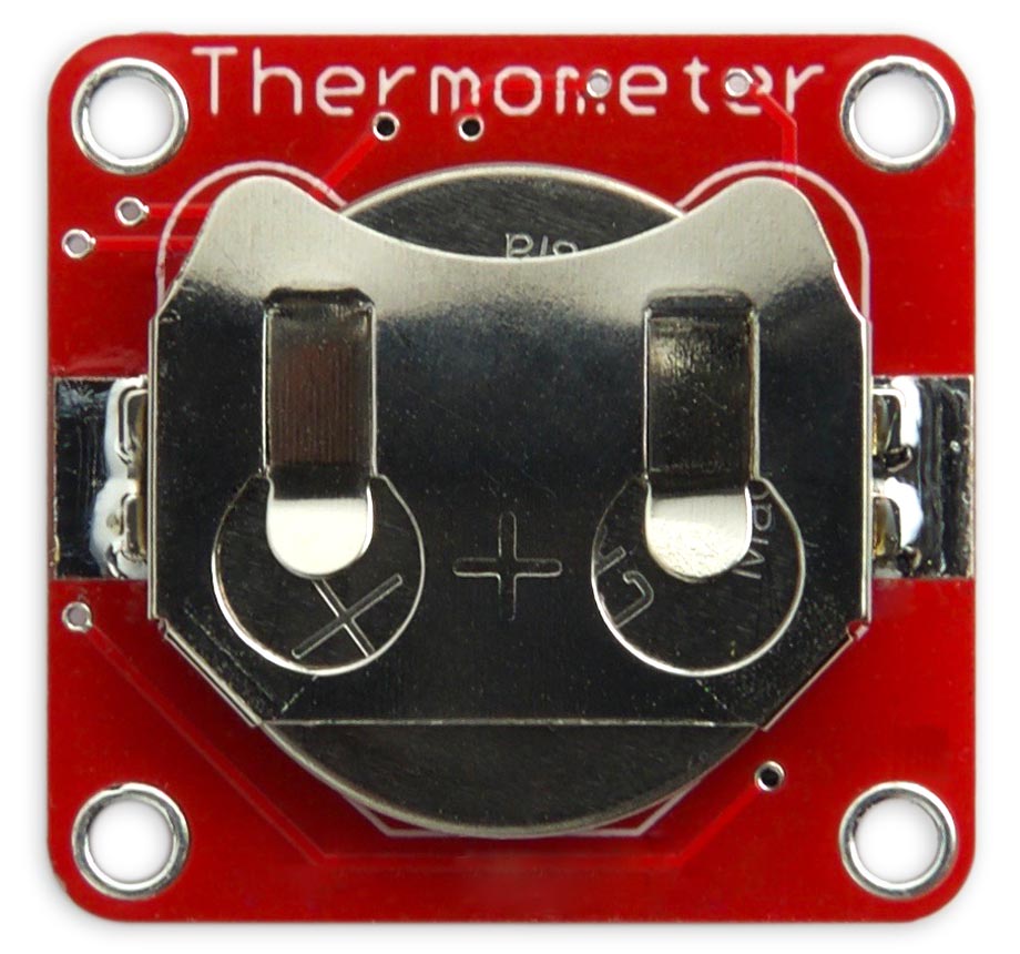
The back of the two-digit thermometer board, showing the CR2032 coin cell.
Note that if you are making this thermometer for a child, please bend the tabs on the coin cell holder, after inserting the cell, so the coin cell can't be removed and swallowed.
The program
The main program stays in sleep mode most of the time to save power, and gets woken up by an interrupt from the watchdog timer.
Reading the temperature sensor
The 1-wire interface to the temperature sensor is based on my earlier Simple 1-Wire Interface, using the ATtiny84’s 16-bit Timer/Counter1 to do the timing. It is set up with a 1MHz clock:
void OneWireSetup () {
  TCCR1A = 0<<WGM10;                   // Normal mode
  TCCR1B = 0<<WGM12 | 2<<CS10;         // Normal mode, divide clock by 8
}
The routine DelayMicros() then gives a delay in a specified number of microseconds by waiting for a compare match with output compare register OCR0A:
void DelayMicros (unsigned int micro) {
  TCNT1 = 0; TIFR1 = 1<<OCF1A;
  OCR1A = micro;
  while ((TIFR1 & 1<<OCF1A) == 0);
}
The routine DisplayTemperature() reads the temperature from the DS18B20 and displays it. Since there is only one device on the bus you can ignore the serial number, and just send a Skip ROM command which sends subsequent commands to any device:
void DisplayTemperature () {
  cli();                                  // No interrupts
  if (OneWireReset() != 0) {
    sei();
    DisplayError(0);                      // Device not found
  } else {
    OneWireWrite(SkipROM);
    OneWireWrite(ConvertT);
    while (OneWireRead() != 0xFF);
    OneWireReset();
    OneWireWrite(SkipROM);
    OneWireWrite(ReadScratchpad);
    OneWireReadBytes(9);
    sei();                                // Interrupts
    if (OneWireCRC(9) == 0) {
      int temp = DataWords[0];
      Display((temp+8)>>4);               // Round to nearest degree
    } else DisplayError(1);               // CRC error
  }
}
The DS18B20 returns the temperature as a signed 16-bit integer in units of 1/16th of a degree. This is rounded to the nearest degree and displayed by calling Display().
Errors
The routine DisplayError() displays errors in the 1-wire interface:
void DisplayError (int no) {
  Buffer[0] = Error;
  Buffer[1] = no;
}
If the 1-wire interface fails to find a 1-wire device on the bus it displays E0. If the 1-wire interface gets a CRC error in the data read from the temperature sensor it displays E1.
Multiplexing the display
As in a few of my previous projects, the display is generated under interrupt, using the contents of the array Buffer[]. For example, to display "20" execute:
Buffer[0]=2; Buffer[1]=0;
The program uses Timer/Counter0 to generate an interrupt at 125Hz, fast enough to avoid flicker, which is used to multiplex the display. It is first configured in setup():
  TCCR0A = 2<<WGM00;                      // CTC mode; count up to OCR0A
  TCCR0B = 0<<WGM02 | 4<<CS00;            // Divide by 256
  OCR0A = 250-1;                          // Compare match at 125Hz
  TIMSK0 = 0;                             // Interrupts initially off
The compare match interrupt service routine calls DisplayNextDigit() and counts down a ticks counter:
ISR(TIM0_COMPA_vect) {
  DisplayNextDigit();
  Ticks--;
}
DisplayNextDigit() reads the data in the appropriate element of Buffer[] and lights the segments in the corresponding display digit. The program uses a #define to cater for both common cathode and common anode displays. If your circuit displays "88" when you first connect power you've probably got this wrong. Here's the common cathode version:
void DisplayNextDigit () {
  PORTB = PORTB | 1<<digit;                    // Turn old digit off
  digit = digit ^ 1;                           // Toggle between 0 and 1
  char segs = charArray[Buffer[digit]];
  PORTA = segs;                                // Lit segments high
  PORTB = PORTB & ~(1<<digit);                 // Turn new digit on
}
Finally, the routine Display() decodes a two-digit number into Buffer[]:
void Display (int n) {
  int units = n % 10;
  int tens = n / 10;
  int temp0 = tens;
  int temp1 = abs(units);
  if (tens < -1) {temp0 = Lo; temp1 = Lo+1; }
  else if (tens > 9) {temp0 = Hi; temp1 = Hi+1; }
  else if (tens == -1) temp0 = Minus1;
  else if ((tens == 0) && (units >= 0)) temp0 = Blank;
  else if ((tens == 0) && (units < 0)) temp0 = Minus;
  Buffer[0] = temp0;
  Buffer[1] = temp1;
}
It handles the special cases of temperatures below -19°C, temperatures between -19°C and -10°C, and temperatures above 99°C.
Saving power
To keep the power consumption as low as possible the program disables the ADC as it isn't used, turns off the clocks to the USI and ADC, and enables the PWR_DOWN sleep mode:
  ADCSRA &= ~(1<<ADEN);                   // Disable ADC to save power
  PRR = 1<<PRUSI | 1<<PRADC;              // Turn off clocks to USI & ADC to save power
  set_sleep_mode(SLEEP_MODE_PWR_DOWN);
The main program
The main program displays the temperature for a tenth of a second, and then goes to sleep. I found that this was about the shortest display time that was clear to read.
I found that it's quite difficult to keep your eyes focussed on the display, without blinking, when you're waiting for the next temperature flash. I therefore added a two-second countdown, which flashes the decimal points in turn, before showing the temperature. This should have a negligible effect on the current consumption:
void loop () {
  Buffer[0] = DP; Buffer[1] = Blank;
  DisplayOn(12);
  WDDelay(6);                              // Sleep for 1 second
  Buffer[0] = Blank; Buffer[1] = DP;
  DisplayOn(12);
  WDDelay(6);                              // Sleep for 1 second
  DisplayTemperature();
  DisplayOn(12);
  WDDelay(9);                              // Sleep for 8 seconds
  WDDelay(9);                              // Sleep for 16 seconds
  WDDelay(9);                              // Sleep for 24 seconds
}
The display remains off for 24 seconds between flashes, using three calls with the watchdog timer's maximum delay of 8 seconds. The current consumption when displaying the temperature is 6.6mA, and when asleep is 4.7µA, so the average current consumption is 1/240 x 6.6mA. The CR2032 button cell has a typical capacity of 225mAh, so the expected life is:
(225/6.6) x 240 / 24 = 340 days, or approximately a year.
Lowest temperature
Given that this circuit might be used at very low temperatures I was interested in the temperature range of the components I used.
The ATtiny84 and LED display are rated at -40°C to +85°C. The DS18B20 and resistors and capacitors are rated at -55°C to +125°C. The limiting factor will be the CR2032 button cell, which is rated at between -20°C and +70°C. You could extend this by using the equivalent BR2032 lithium-carbon monofluoride button cell which is rated between -30°C to +85°C.
Compiling the program
I compiled the program using Spence Konde's ATTiny Core [10]. Choose the ATtiny24/44/84 option under the ATTinyCore heading on the Board menu. Then check that the subsequent options are set as follows (ignore any other options):
Chip: "ATtiny84"
Clock: "8 MHz (internal)"
B.O.D: "B.O.D. Disabled"
Pin Mapping: "Clockwise (like damellis core)"
To program the PCB version I connected to the ATtiny84 using a Pomona test clip that fitted to the top of the chip [11], using the Sparkfun Tiny AVR Programmer [12]. Choose Burn Bootloader to set the fuses appropriately, then choose Upload to upload the program.
Here's the whole Two-Digit Thermometer program: Two-Digit Thermometer Program.
Or get the source from GitHub, together with the Eagle files for the PCB so you can make yourself a board, at: https://github.com/technoblogy/two-digit-thermometer.
Or order a board from OSH Park here: Two-Digit Thermometer Board.
- ^ Breadboard - Mini Modular on SparkFun.
- ^ Mini Breadboard from HobbyTronics.
- ^ PCBWay PCB prototyping service.
- ^ Maxim DS18B20U+ Temperature Sensor on RS-Online.
- ^ 5pcs DS18B20 MSOP8 on AliExpress.
- ^ KCDA39-105 Kingbright 2 Digit 7-Segment LED Display Red on RS-Online.
- ^ KCDA39-107 Kingbright 2 Digit 7-Segment LED Display Yellow on RS-Online.
- ^ Coin Cell Battery Holder - 20mm (SMD) on SparkFun.
- ^ Coin Cell Battery Holder - 20mm (SMD) on Proto-PIC.
- ^ ATTinyCore on GitHub.
- ^ IC Test Clip SOJ SOIC 14 Contacts on Farnell.
- ^ Tiny AVR Programmer on Sparkfun.
blog comments powered by Disqus