Continuity Tester
18th November 2017
This article describes a simple continuity tester, based on an ATtiny85 and a piezo buzzer, designed for checking circuit wiring, or tracing out the tracks on a PCB:
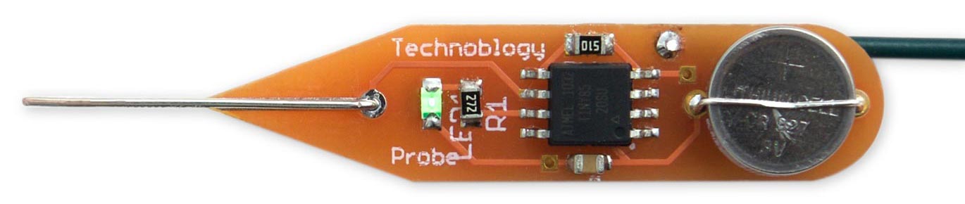
Continuity Tester based on an ATtiny85. The piezo buzzer is on the reverse of the board.
It has a low threshold resistance of 50Ω to avoid false positives, and passes less than 0.1mA through the circuit under test, to avoid affecting sensitive components. It's powered from a small button cell, and automatically switches itself off when not in use, avoiding the need for an on/off switch.
Introduction
I recently designed a PCB with very fine tracks for a project I'm planning for a future article, and thought it would be useful to have a small, portable continuity tester to help check for solder bridges on the SMD soldering. Although most multimeters include a continuity tester mode, I wanted to design a stand-alone tool with the following advantages:
- Smaller and more convenient than a multimeter.
- Low threshold resistance of 50Ω, avoiding false positives due to other components in the circuit.
- Fast response, so you can drag the probe across a line of pins to detect shorts.
- Low current, to avoid affecting sensitive components in the circuit under test. This circuit passes only 100µA through the probes, which is a factor of 10 less than most multimeters.
- No on/off switch, so there's no danger of leaving it switched on and running down the battery. The circuit automatically goes to sleep if it's unused for 60 seconds, and the standby power consumption is less than 1µA, giving a battery life of several years.
An LED shows when the circuit is switched on; this is optional, but I like having confirmation that it's working.
At first sight, using a microcontroller for this application seems overkill; however, I think it would take quite a complex circuit of discrete components to meet all of these requirements.
How it works
The Continuity Tester uses the Analog Comparator in the ATtiny85 to detect the voltage on the probe; in fact, it's the first project I've built that's used the analog comparator. The circuit is equivalent to this:
Equivalent circuit of the continuity tester using the ATtiny85 analogue comparator.
When the voltage on the positive pin AIN0 is higher than the voltage on the negative pin AIN1, the Analog Comparator output, ACO, is set. Assuming a 5V supply, the voltage at AIN1 is held at 5V by the pullup resistor, and the voltage at AIN0 is held at 5mV by the resistor divider. If the resistance between the probes becomes less than 50Ω, the voltage on AIN1 will be lower than the voltage on AIN0, taking the output of the comparator high. This is then used to enable the oscillator driving the piezo speaker.
The advantage of using the analog comparator rather than a regular digital input is that it allows us to precisely set the point at which the input will be triggered.
In fact the two pullup resistors are unnecessary, as we can use the internal pullups on the inputs corresponding to AIN0 and AIN1. This has two benefits; first, it saves two resistors, but more importantly, it allows us to turn off the pullup on AIN0 when the processor goes to sleep, avoiding the current drain through the 50Ω resistor.
The circuit
Here's the complete circuit of the Continuity Tester:
Circuit of the continuity tester, based on an ATtiny85.
I built a prototype on a mini breadboard using through-hole components to test out the circuit:
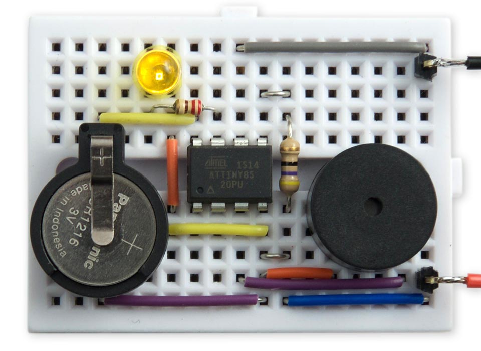
Construction
For the final version I designed a board in Eagle and sent it to Ragworm in the UK for fabrication [1]:
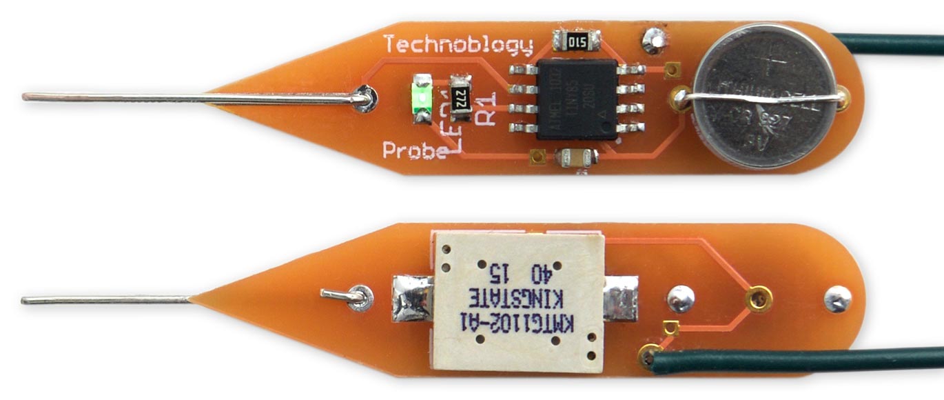
The front and back of the completed Continuity Tester circuit board.
I recommend using the ATtiny85V variant of the processor as this is rated down to 1.8V, so it will extend the life as the battery fades. The ATtiny85 is an SOIC package, and the resistors and LED are 0805 SMT components. The resistor values aren't critical; I chose standard values I had in my kit of resistors.
The piezo speaker is the smallest SMD piezo I could find [2]. The circuit is powered by a CR927 cell, and this is held in place by a tinned copper wire strap, soldered in position, avoiding the need for a battery holder. For the probe I used a length of thicker tinned copper wire soldered to the board. For the ground probe I used a crimp pin on a 20cm flying lead, or you could use a multimeter probe.
I encapsulated the finished board in clear heatshrink tubing [3] to protect the components. Alternatively if you don't want to make a PCB you could construct it on a piece of Veroboard using a PDIP ATtiny85 and through-hole components.
The program
The program uses Timer/Counter1 to generate the beep through the piezo speaker. This is set up in setup() using the following commands:
  TCCR1 = 1<<CTC1 | 0<<COM1A0 | 0<<CS10;  // CTC mode, counter stopped
  GTCCR = 1<<COM1B0;                      // Toggle OC1B (PB4)
  OCR1C = 119;                            // Plays 1042Hz (C6)
I chose the frequency that sounded loudest through the piezo speaker I was using.
The setup() routine also enables a pin-change interrupt on the Probe input:
  PCMSK = 1<<Probe;                       // Pin change interrupt on Probe
  GIMSK = GIMSK | 1<<PCIE;                // Enable pin-change interrupt
A change on the Probe input calls the interrupt service routine, which resets the timer:
ISR (PCINT0_vect) {
  Time = millis();
}
The main loop, loop(), then repeatedly checks the analog comparator output AC0 in register ACSR, and plays the beep if the comparator is enabled:
  bool Sense = ACSR>>ACO & 1;
  if (Sense) Beep(); else NoBeep();
The routines Beep() and NoBeep() simply enable or disable Timer/Counter1:
void Beep () {
  TCCR1 = TCCR1 | 3;                      // Counter = clock/4
}

void NoBeep () {
  TCCR1 = TCCR1 & ~3;                     // Counter stopped
}
To avoid the need for an on/off switch the circuit automatically puts the processor to sleep if more than 60 seconds have elapsed, specified by the constant Timeout. This is handled by the following code in loop():
  if (millis() - Time > Timeout) {
    digitalWrite(LED, false);    // LED off
    pinMode(Reference, INPUT);   // Turn off pullup to save power
    sleep_enable();
    sleep_cpu();
    // Carry on here when we wake up
    pinMode(Reference, INPUT_PULLUP);
    digitalWrite(LED, true);    // LED on
  }
Before putting the processor to sleep this code turns off the LED, and disables the Reference pullup resistor to save power. Any low level on the probe, even if it's not low enough resistance to activate the comparator, will generate a pin-change interrupt and reset the timer, or wake up the processor if it's asleep.
Compiling the program
I compiled the program using Spence Konde's ATTiny Core [4]. Select the ATtiny x5 series option under the ATtinyCore heading on the Boards menu. Then choose Timer 1 Clock: CPU, B.O.D. Disabled, ATtiny85, 1 MHz (internal) from the subsequent menus; this is the default fuse setting on a new ATTiny85.
I connected to the ATtiny85 using a clip that fitted to the top of the chip [5], using the Sparkfun Tiny AVR Programmer [6]. Choose Burn Bootloader to set the fuses appropriately, if necessary, and then choose Upload to upload the program.
Note that I recommend programming the ATtiny85 before fitting the 51Ω resistor to the circuit, as this may interfere with the ISP. This seems to be dependent on which programmer you are using.
Here's the whole Continuity Tester program: Continuity Tester Program.
Alternatively, get it on GitHub here together with the Eagle files for the PCB: Continuity Tester on GitHub.
Or order a board from OSH Park here: Continuity Tester Board.
Update
2nd April 2018: Added a note about using the ATtiny85V.
- ^ Ragworm PCB prototyping service.
- ^ Kingstate KMTG1102-A1 on RS-Online.
- ^ TE Connectivity Clear Heat Shrink Tubing 2:1 12.7mm Dia on RS-Online.
- ^ ATTinyCore on GitHub.
- ^ IC test Clip - SOIC 8-pin on SparkFun.
- ^ Tiny AVR Programmer on Sparkfun.
blog comments powered by Disqus