Simple GPS Odometer
29th December 2014
This project describes a simple odometer, or mileometer, using a GSP module to measure the distance you have walked or driven. It uses an ATtiny2313 to display the total in miles or kilometers, with a resolution of a hundredth of a mile/kilometer, on a miniature four-digit 7-segment bubble display:
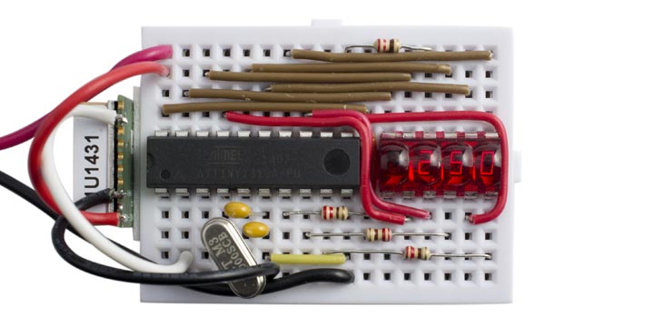
Simple GPS Odometer based on an ATtiny2313. We've travelled 2.5 miles.
One way to measure the distance travelled is to regularly calculate the distance from your last location (latitude and longitude) to your current location, and then keep a running total of these distances. This is the method used by some other odometer projects, but it requires tricky floating-point or fixed-point calculations.
There's actually a much simpler way. The GPS module regularly provides the instantaneous speed (in knots). To get the distance travelled we simply integrate this, or keep a running total of the speed multiplied by the time between readings. The arithmetic is now a simple multiplication and addition.
Circuit
Although I could have implemented this odometer using the same circuit as my earlier Tiny GPS Speedometer [Updated], I decided to base this on Sparkfun's tiny four-digit bubble display [1] but unfortunately they are now discontinued. You may occasionally be able to find them on eBay. To drive it directly from the processor I needed at least 15 I/O lines; eight for the segments plus decimal point, four for the digits, plus two for the crystal and one for the GPS input. The ideal choice seemed to be the ATtiny2313, which has the added bonus of including a USART to receive the NMEA messages from the GPS module.
For this application I used a cheap GPS module, the Gtop010 (also known as GTPA010 or PA6C) available from PV Electronics for under £20 in the UK [2]. Alternatively, the similar Gtop013 (or PA6H) is available from Adafruit [3], or you could use their breadboard-friendly Ultimate GPS Breakout [4].
Here's the complete circuit:
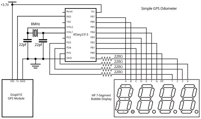
Simple GPS Odometer circuit.
The wiring between the ATtiny2313 I/O ports and 7-segment display may look a bit arbitrary, but it was chosen to make the connections simpler on the breadboard; the actual assignments are taken care of by the software as explained below. The only restriction is that each segment should be connected to a pin on Port B.
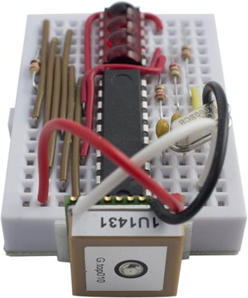
It all fitted onto a mini breadboard, with the GPS module secured to one end with a piece of double-sided sticky tape:
Multiplexing the display
The display is generated under interrupt, using the contents of the array Buffer[]. For example, to display "7890" execute:
Buffer[0]=7; Buffer[1]=8; Buffer[2]=9; Buffer[3]=0;
The program uses Counter/Timer1 to generate an interrupt at 200Hz, which is used to multiplex the display. To make it easier to wire up the circuit on the breadboard I connected the segments to arbitrary pins on Port B. The array Segments[] specifies how they are wired, and the routine ReorderBits() then reorders the bits in the segment definitions to account for this:
void ReorderBits() {
  char segs, newsegs;
  for (int i=0; i<charArrayLen; i++) {
    segs = charArray[i];
    newsegs = 0;
    for (int i=0; i<8; i++) {
      newsegs = newsegs | ((segs & 1)<<Segments[i]);
      segs = segs >> 1;
    }
    charArray[i]=newsegs;
  }
}
You could omit the need for this routine, and save program space, by wiring the segments to specific I/O pins: G to PB0, F to PB1, etc, and DP to PB7.
Counter/Timer1 is then configured in setup():
  TCCR1A = 0<<WGM10;
  TCCR1B = 1<<WGM12 | 2<<CS10;  // Divide by 8
  OCR1A = 4999;                 // Compare match at 200Hz
  TIMSK |= 1<<OCIE1A;           // Compare match interrupt enable
The compare match interrupt service routine then simply calls DisplayNextDigit():
ISR (TIMER1_COMPA_vect) {
  DisplayNextDigit();
}
This reads the data in the appropriate element of Buffer[] and lights the segments in the corresponding display digit:
void DisplayNextDigit() {
  pinMode(Digits[digit], INPUT);
  digit = (digit+1) % 4;
  char segs = charArray[Buffer[digit]];
  // Display decimal point?
  if (digit == dp) segs = segs | (1<<Segments[7]);
  DDRB = 0;     // All inputs
  PORTB = segs; // 1 = high
  DDRB = segs;  // 1 = output
  pinMode(Digits[digit], OUTPUT);
  digitalWrite(Digits[digit], LOW);
}
Finally, the display converts an unsigned integer to the appropriate four-digit decimal number in Buffer[], with leading-zero suppression. Numbers up to 9999 are displayed with two decimal places; for example, 123 is displayed as "1.23". Numbers greater than 9999 are displayed with one decimal place; for example, 12345 is displayed as "123.4". The largest number that can be displayed is "655.3":
void Display (unsigned int number) {
  boolean dig = false;
  int j;
  if (number>9999) { j=10000; dp=2; }
  else { j=1000; dp=1; }
  for (int d=0; d<4 ; d++) {
    int i = (number/j) % 10;
    if (!i && !dig && j>100) Buffer[d]=Space;
    else { Buffer[d]=i; dig = true; }
    j=j/10;
  }
}
Reading the GPS data
The NMEA data is read from the GPS module using the ATtiny2313 USART. This is first configured in setup():
  UCSRB = 1<<RXEN | 1<<RXCIE;   // Enable Rx and interrupt
  UCSRC = 3<<UCSZ0;             // 8-bit UART mode
  UBRRL = 51;                   // 9600 baud
When a character has been received by the USART an interrupt is generated, and the interrupt service routine simply calls ParseGPS() with the contents of the USART data register:
ISR (USART_RX_vect) {
  char c = UDR;
  ParseGPS(c);
}
This calls ParseGPS() to process the received character, which is a cut-down version of my earlier Minimal GPS Parser [Updated]. The ATtiny2313 is a bit limited in program space (2K bytes) and RAM space (128 bytes), and although there's an ATtiny4313 that has double these sizes, it's not properly supported by the Arduino IDE. To get the program to work with the ATtiny2313 I removed the parts of the GPS parser for reading the latitude, longitude, course, and date which aren't needed for this application, and I moved the format string fmt[] into program memory to reduce the amount of RAM needed:
// Example: $GPRMC,194509.000,A,4042.6142,N,07400.4168,W,2.03,221.11,160412,,,A*77
PROGMEM prog_uchar fmt[]=
           "$GPRMC,dddtdd.ddm,A,????.????,?,?????.????,?,djdk,???.??,??????,,,?*??";

int state = 0;
unsigned int temp;

// GPS variables
volatile unsigned int Time, Msecs, Knots;
volatile boolean Fix;

void ParseGPS (char c) {
  if (c == '$') { state = 0; temp = 0; }
  char mode = pgm_read_byte_near(fmt + state++);
  // If received character matches format string, or format is '?' - return
  if ((mode == c) || (mode == '?')) return;
  // d=decimal digit
  char d = c - '0';
  if (mode == 'd') temp = temp*10 + d;
  // t=Time - hhmm
  else if (mode == 't') { Time = temp*10 + d; temp = 0; }
  // m=Millisecs
  else if (mode == 'm') { Msecs = temp*10 + d; temp = 0; }
  // j/k=Speed - in knots*100
  else if (mode == 'j') { if (c != '.') { temp = temp*10 + d; state--; } }
  else if (mode == 'k') { Knots = temp*10 + d; Fix = 1; }
  else state = 0;
}
The main loop simply waits for Fix to be 1, indicating that another GPS NMEA sentence has been received, reads the speed in knots*100, and adds it to Distance. It then displays the distance suitably scaled:
void loop() {
  long temp, Distance;
  // Wait for fresh data
  do ; while(!Fix);
  cli(); temp = Knots; sei();
  Distance = Distance + temp;
  Display(Distance*19/59438);
  Fix = 0;
}
We could use millis() to read the speed once a second, but because the GPS module outputs readings at precise one-second intervals we can simply wait for each updated reading.
To display the distance in miles to two decimal places, the speed in knots over one second is multiplied by 1.150779 (the number of miles per hour equivalent to a knot) and divided by 3600 (the number of seconds in an hour); 19/59438 gives a good rational approximation to this. Note that the GPS module can give small speed values even when you are stationary; to avoid these accumulating to give an apparent distance reading the program ignores speed values less than 100 (1 knot).
To display the distance in kilometers with two decimal places, the speed in knots should be multiplied by 1.852 and divided by 3600; a good rational approximation to this is 13/25270, so to display kilometers per hour change the call to Display() to:
Display(Distance*13/25270);
The final program uses 1902 of the available 2048 bytes. See the end of the article for a link to the whole program.
Uploading the program
I compiled the program using the Arduino IDE and used the Tiny AVR Programmer [5] to upload it to the ATtiny2313 on the breadboard; see ATtiny-Based Beginner's Kit. Plug the Tiny AVR Programmer into the computer's USB port, and then connect it to the ATtiny2313 using six jumper wires:
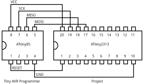
Connecting the Tiny AVR Programmer to the ATtiny2313.
I compiled the program using the ATtiny core extension to the Arduino IDE [6]. This doesn't include a setting for the ATtiny2313 with an 8MHz crystal, so I added the following definition to the boards.txt file:
###########################################################################

attiny2313at8x.name=ATtiny2313 @ 8 MHz (external crystal; BOD disabled)

attiny2313at8x.upload.using=arduino:arduinoisp
attiny2313at8x.upload.maximum_size=2048

# Ext. Crystal Osc. 8.0 MHz; Start-up time: 14 CK + 65 ms; [CKSEL=1111 SUT=11]
# Brown-out detection disabled; [BODLEVEL=111]
# Serial program downloading (SPI) enabled; [SPIEN=0]
# Preserve EEPROM memory through the Chip Erase cycle; [EESAVE=0]

attiny2313at8x.bootloader.low_fuses=0xFF
attiny2313at8x.bootloader.high_fuses=0x9F
attiny2313at8x.bootloader.extended_fuses=0xFF
attiny2313at8x.bootloader.path=empty
attiny2313at8x.bootloader.file=empty2313at8.hex

attiny2313at8x.build.mcu=attiny2313
attiny2313at8x.build.f_cpu=8000000L
attiny2313at8x.build.core=tiny

###########################################################################
This adds an ATtiny2313 @ 8MHz (external crystal; BOD disabled) option to the Board submenu. Select this, and choose Burn Bootloader to program the ATtiny2313 fuses for an 8MHz external crystal. Then upload the program to the ATtiny2313.
Note: The GPS module is rated at a maximum supply voltage of 4.3V, so you should disconnect it from the circuit while programming the ATtiny2313 using the Tiny AVR Programmer, which supplies 5V to the circuit.
The circuit was powered by a 3.7V LIPO battery, and the total current consumption was about 30-40mA. I tested the project by taking it for a drive in the car, and verified that the reading closely matched the car's odometer.
Here's the whole Simple GPS Odometer program: Simple GPS Odometer Program.
Other applications
It would be a simple extension to add buttons to the two spare I/O lines to allow you to change the display to show speed or current time in addition to distance. Add a button between Reset and GND to allow you to reset the odometer to zero.
Addendum
6th April 2015: Added a note about disconnecting the GPS module when powering from a computer.
- ^ Bubble Display on Sparkfun.
- ^ Micro GPS Module on PV Electronics.
- ^ Ultimate GPS Module on Adafruit.
- ^ Ultimate GPS Breakout on Adafruit.
- ^ Tiny AVR Programmer on SparkFun.
- ^ ATtiny core for Arduino: arduino-tiny on Google Code.
blog comments powered by Disqus