Number Maze Game
21st December 2022
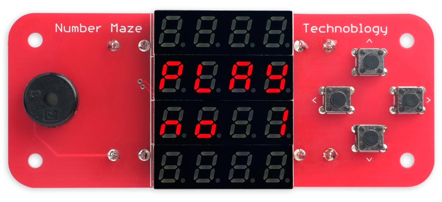
This is a handheld game that displays a 4x4 matrix of numbers representing a logic maze, and you have to solve the maze by pressing the buttons:
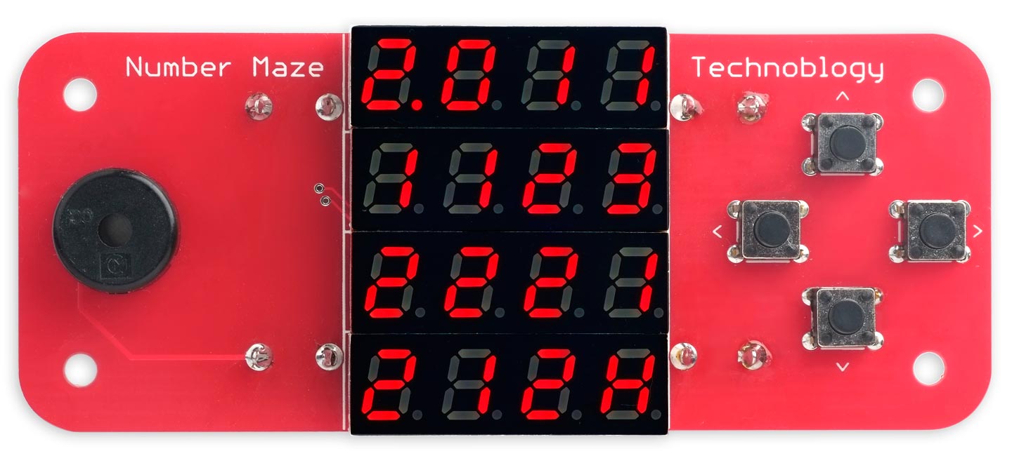
The Number Maze Game, based on an AVR128DA32, in which you have to navigate to Home using the arrow buttons.
Your position in the maze is shown by the decimal point, and you can move it around the maze using the four arrow buttons. If you get to Home, labelled H, the speaker plays a tune, and you can then move to the next maze. The game contains a series of 12 different mazes of increasing difficulty.
It's based on four low-cost 4-digit seven-segment displays controlled by an AVR128DA32 microcontroller, and it's powered by two AA cells.
Introduction
At about this time of year I try and think of a game project to build as a present for one or two younger friends and relations. This year I've come up with an electronic version of a classic type of logic maze, called a Number Maze or Jumping Maze [1]. You start on an initial square, and the number on each square shows how far you can jump from that square horizontally or vertically. The aim is to reach a goal in the smallest number of steps.
Here's a simple example. In fact this is the first maze that the Number Maze game shows you. Start at the top left cell, and find a route to the bottom right cell marked H (for Home):
Here's the answer, which takes seven steps:
Although I could have designed it using a small square OLED or TFT display, I thought it would be more fun to base it on four 4-digit seven-segment display modules.
How the Number Maze Game works
The Number Maze Game presents the maze by lighting up 16 digits on the LED displays. You start from the top left square, and navigate through the maze by pressing the four pushbuttons. Your current position in the maze is shown by a decimal point. When you reach home, the square marked H, the speaker plays a tune.
Pressing the right button then takes you to the next introductory screen, and a further press shows the next maze. Alternatively, the left button takes you back to the first maze.
If at any point you get stuck, such as by moving onto a cell containing a 0, keeping any button held down acts as undo, successively stepping you back through your previous positions in the maze.
The game includes 12 mazes, in approximate order of difficulty, and you can easily add additional ones of your own.
There's no on/off switch, but if you don't press any button for a minute the game goes into low-power sleep, with a consumption of less than 1µA. Press any button to wake the game up again.
The circuit
Here's the circuit:
Circuit of the Number Maze Game, based on four 4-digit seven-segment displays controlled by an AVR128DA32.
As there are a lot of interconnections I decided to go straight to designing a PCB for it, rather than attempting to prototype it on a breadboard.
I originally wanted to design the circuit entirely using through-hole components, so it could be soldered together using an ordinary soldering iron. However, the game needs to have 16 displays, each of which has seven segments and a decimal point, so that's 24 I/O lines to begin with. Then we need at least one additional I/O line for the pushbuttons and one for the speaker, making 26. This rules out an ATmega328P, which only provides 22, and the 40-pin PDIP ATmega1284P would make the PCB too large.
I therefore chose a 32-pin TQFP AVR128DA32 microcontroller, which provides 26 I/O lines, exactly what we need. The 7x7mm TQFP package has leads protruding from a square body, making it possible to solder it with a thin-tipped soldering iron if you're careful, although I used a hot-air gun. The program uses only about 3K bytes of flash and 300 bytes of RAM, so the AVR32DA32 and AVR64DA32 should be fine. Note that the 32-pin AVR DB-series and DD-series parts are not suitable, because they redefine the pin at the PD0 position as VDDIO2 for the Multi-Voltage IO (MVIO) feature.
Apart from the difference in memory sizes, the older ATmega4808 is surprisingly similar to the AVR128DA32, and has similar peripherals. It is available in the same 32-pin TQFP package, with an identical pinout, so it is a drop-in replacement, and I was surprised that the same program works perfectly with only a minor change, handled by a #define. Again, the ATmega808, ATmega1608, or ATmega3208 should also be suitable.
The LED displays are four-digit seven-segment 0.28" type 2841AS (common cathode), available for under $1/£1 each from a couple of different vendors on AliExpress, or if you don't want to wait for delivery from China you can probably find them from a local vendor on eBay. Their low cost reflects the fact that they are now considered old-school compared to the more recent alternatives such as OLED and TFT displays. However they are fun, robust, and ideal for a game like this. Be careful not to buy the similar-looking four-digit seven-segment 0.28" displays that include a colon, because in these the decimal points aren't functional, and the decimal points are needed by this game.
The circuit is designed to be powered by two AA cells, and the board is designed for PCB-mounting clips. The Schottky diode protects the circuit in case the two AA cells are inserted the wrong way round, but if you prefer to live dangerously you can leave it out and insert a link instead.
► Parts list
Construction
I designed a board in Eagle and sent it to PCBWay [2] for fabrication. I chose red PCBs to match the red displays.
I soldered the SMD components on the back of the board using a Youyue 858D+ hot air gun set to 275°C. I then mounted the displays, pushbuttons, and piezo speaker on the front of the board using a conventional soldering iron. You need to trim the display leads with a pair of side cutters after soldering them to make sure they don't make contact with the AA cells. Finally mount the four battery clips on the back of the board, using a generous amount of solder to hold them firmly in place:
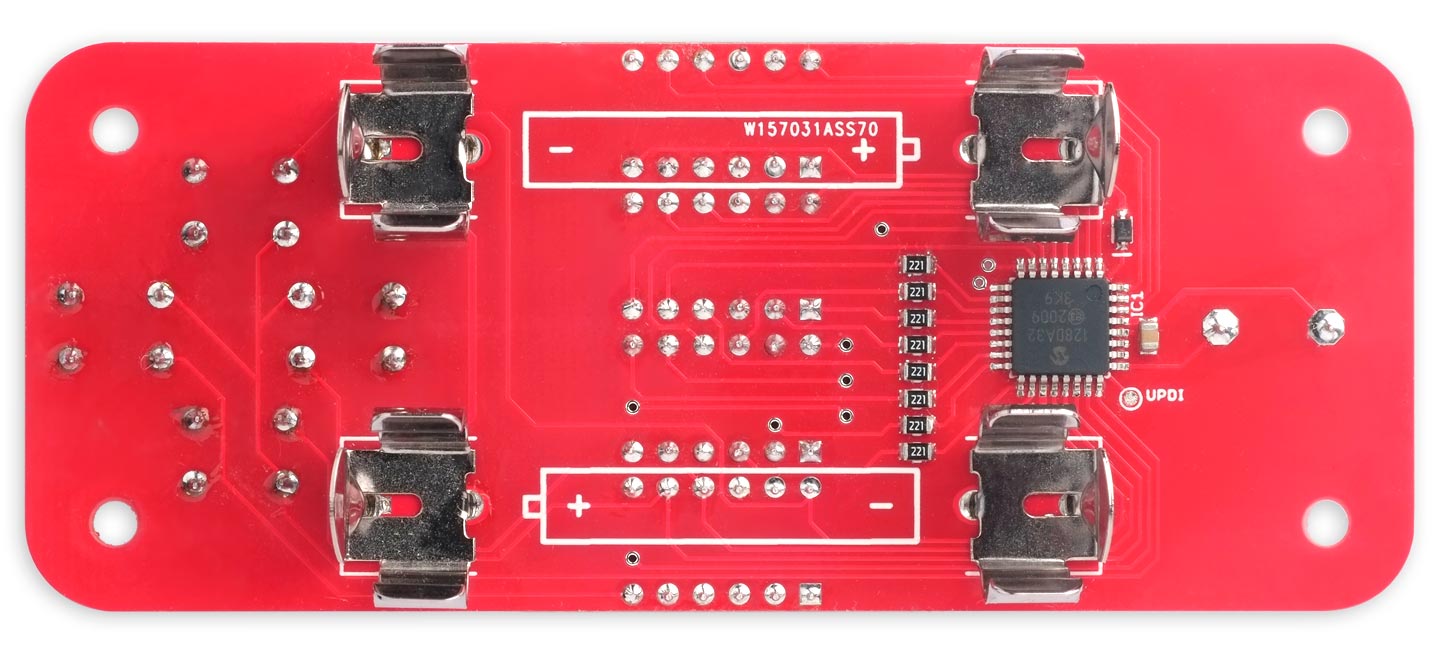
Back of the Number Maze Game, showing the AA battery clips and the AVR128DA32 processor.
On my prototype PCB I didn't allow quite enough spacing between the displays, so I had to sand a small thickness off them to fit them in the board. I've fixed this in a revised version of the PCB, given in the resources below, and I've also added a 3-pin pad for the UPDI programming connections so you can attach a three-way 0.1 pitch SMD header socket if you want to.
You could use a second identical PCB as a back panel, held in place with four threaded pillars and M3 screws.
The program
The mazes
I've provided 12 mazes, approximately increasing in difficulty, and they are defined by the two-dimensional array mazes[][]:
const int TotalMazes = 12;

uint8_t mazes[TotalMazes][17] = {
  "201111232221212H", // 7 8+5
  "3212122112H21213", // 7 7+4
  "121213122132213H", // 8 9+3
  "221121112222111H", // 8 9b+3
  "131212131131232H", // 9 9+2
  "112213123122112H", // 9 10+4
  "1313213221H22332", // 10 8+3
  "231111333113332H", // 10 9+0
  "3131221212H33133", // 10 9+2
  "222231131321112H", // 10 10+1
  "223121212121112H", // 11 8+3
  "212331013310132H"  // 11 8b+0
};
I chose to represent each maze as a string of ASCII characters, and there's a translation table to convert each ASCII character to the appropriate segment pattern:
uint8_t symbol[]  = { '0',  '1',  '2',  '3',  '4',  '5',  '6',  '7',  '8',  '9',
                      ' ',  'H',  'P', 'L',  'A',  'Y',   'n',  'o',  0xff };
uint8_t segment[] = { 0x7e, 0x30, 0x6d, 0x79, 0x33, 0x5b, 0x5f, 0x70, 0x7f, 0x7b,
                      0x00, 0x37, 0x67, 0x0e, 0x77, 0x3b, 0x15, 0x1d, 0xff };
It's quite a struggle finding text that you can display on the seven-segment displays; "MAZE" is unfortunately not possible. I've chosen the text "PLAY no x" to introduce each new maze:
The Number Maze Game intro screen.
The segment patterns for these characters are included in the table.
The routine Segments() converts an ASCII character to the corresponding seven-segment pattern:
uint8_t Segments (uint8_t c) {
  int p = 0;
  while (symbol[p] != 0xff) {
    if (symbol[p] == c) return segment[p];
    p++;
  }
  return 0;
}
The display wiring
The following table shows how the matrix of 16 LED displays are wired up to the I/O pins on the AVR128DA32:
The matrix of 7-segment displays is multiplexed by a timer interrupt, using the 16-bit Timer/Counter TCB0 to generate an interrupt at 1600Hz. Each display is therefore updated at 100Hz, which is fast enough to avoid flicker.
The displays are set up by the routine SetupDisplay():
void SetupDisplay () {
  // Cathodes input low
  PORTA.DIRCLR = 0xff; PORTA.OUTCLR = 0xff;                // PA0 to PA7
  PORTC.DIRCLR = 0x0f; PORTC.OUTCLR = 0x0f;                // PC0 to PC3
  PORTF.DIRCLR = 0x0f; PORTF.OUTCLR = 0x0f;                // PF0 to PF3
  // Anodes output low
  PORTD.DIRSET = 0xff; PORTD.OUTCLR = 0xff;                // PD0 to PD7
  // Set up Timer/Counter TCB to multiplex the display
  TCB0.CCMP = 2499;                                        // 4MHz/2500 = 1600Hz
  TCB0.CTRLA = TCB_CLKSEL_DIV1_gc | TCB_ENABLE_bm;         // Divide timer by 1
  TCB0.CTRLB = 0;                                          // Periodic Interrupt
  TCB0.INTCTRL = TCB_CAPT_bm;                              // Enable interrupt
}
Initially all the 16 cathodes are defined as inputs, and the anodes as low outputs. The multiplexed display is created by calls to DisplayNextDigit():
void DisplayNextDigit() {
  static uint8_t digit = 0;
  pinMode(cathode[digit], INPUT);
  digit = (digit + 1) & 0xF;
  uint8_t bits = Segments(Buffer[digit]);
  if (digit == Player) bits = bits + 0x80;                 // Decimal point
  PORTD.OUT = bits;
  pinMode(cathode[digit], OUTPUT);
  HandleButtons(digit);
}
This steps through the digits in turn, and for each digit it does the following steps:
- Make the cathode of the previous digit an input.
- Write the segment pattern for the current digit to the common anodes on PORT D.
- Make the cathode of the current digit a low output.
It also calls HandleButtons() to handle button presses on the four pushbuttons.
You may be wondering why I define the unused cathodes as inputs, rather than just make them high outputs. The reason is that if the player were to hold down two buttons at once, this would potentially short a low output with a high output, leading to high power consumption; making them inputs avoids this problem.
Handling the buttons
The pushbuttons are connected to the digit strobe lines for digits 12 to 15, and the input PF4 defined with a pullup detects when one of these lines is pulled low, indicating that the corresponding button has been pressed.
Here's the whole button handling routine:
void HandleButtons (uint8_t digit) {
  static uint8_t press = 0, last = 0, count = 0, move = 0;
  static uint8_t undo[UndoBuffer];
  if (digit >= 12 && digitalRead(24) == 0) {
    press = digit;
    count++;
  }
  if (digit == 15) {
    if (count > 100) {                                     // Long press 1 second
      // Long press = undo
      if (move > 0) {
        move--;
        Player = undo[move];
        Sound = Sound | 1<<UNDO;
      }
      count = 0;
    } else if (press != 0 && press != last) {
      if (Player == 16) {                                  // Intro screen
        // Start new maze
        Player = 0; Buffer = mazes[Maze]; move = 0;
      } else if (mazes[Maze][Player] == 'H') {             // Player on Home
        // Proceed after finishing a level
        NextLevel(press);
      } else {
        // Move player
        int dir = press-12; // Up = 0, Left = 1, Down = 2, Right = 3
        int cell = mazes[Maze][Player];
        int mex = Player & 0x03, mey = Player>>2;
        int nex = mex + (dir%2) * (dir-2) * (cell-'0');
        int ney = mey + (1-dir%2) * (dir-1) * (cell-'0');
        if (nex != mex && nex >= 0 && nex <= 3) {          // Move horizontally
          mex = nex; Sound = Sound | 1<<HORIZONTAL;
          undo[move] = Player; if (move < UndoBuffer-1) move++;
        } else if (ney != mey && ney >= 0 && ney <= 3) {   // Move vertically
          mey = ney; Sound = Sound | 1<<VERTICAL;
          undo[move] = Player; if (move < UndoBuffer-1) move++;
        }
        Player = mey<<2 | mex;
        // Moved onto Home
        if (mazes[Maze][Player] == 'H') Sound = Sound | 1<<SOLVED;
        count = 0;
      }
    }
    last = press;
    press = 0;
  }
}
It calls NextLevel() to move to the next maze:
void NextLevel (uint8_t press) {
  if (press - 12 == 1) Maze = 0;                           // Left button resets to 1
  else Maze = (Maze + 1) % TotalMazes;                     // Wrap around
  Buffer = intro;
  Buffer[11] = (Maze+1)%10 + '0';
  int tens = (Maze+1)/10;
  if (tens == 0) Buffer[10] = ' '; else Buffer[10] = tens + '0';
  Player = 16;                                             // Go to Intro screen
}
Sound effects
The Number Maze Game includes a piezo speaker on I/O line PF5, and I've included a simple tone generator routine to give a beep on each button press, and play a short phrase on completing each maze.
The tone generator is configured by SetupNote():
void SetupNote () {
  PORTF.DIRSET = PIN5_bm;                                  // PF5 as output
  PORTMUX.TCAROUTEA = PORTMUX_TCA0_PORTF_gc;               // PWM on port F
  TCA0.SINGLE.CTRLD = TCA_SINGLE_SPLITM_bm;
  TCA0.SPLIT.CTRLA = TCA_SPLIT_ENABLE_bm | 5<<TCA_SPLIT_CLKSEL_gp; // DIV64
  TCA0.SPLIT.CTRLB = TCA_SPLIT_HCMP2EN_bm;                 // Note on WO5 = PF5
  TCA0.SPLIT.HCMP2 = 0;
}
This first reassigns Timer/Counter TCA0 to PORT F, so waveform generation is available on PF5, and then sets up the Timer/Counter in split mode, with the 4MHz clock divided by 64.
Notes are then generated by routine PlayNote(), which takes a note number between 0 and 11, and a duration in milliseconds:
void PlayNote (int note, int millis) {
  TCA0.SPLIT.HPER = scale[note];
  TCA0.SPLIT.HCMP2 = scale[note]>>1;
  delay(millis);
  TCA0.SPLIT.HCMP2 = 0;
}
This uses the divisors in the array scale[] to give a well-tempered scale:
uint8_t scale[] = {239,226,213,201,190,179,169,160,151,142,134,127};
Putting the game to sleep
The main program loop, in loop(), detects if the interrupt service routine has set the global variable Sound, and asynchronously plays the appropriate sound effect.
It also detects whether Timeout milliseconds have elapsed since the last button-press sound. If so, the following actions are taken:
- The timer interrupt used for multiplexing the display is disabled.
- The I/O lines used for the anodes and cathodes of the displays are defined as low outputs, to minimise power consumption.
- The pushbutton input, PF4, is defined with a input sense interrupt.
- The processor is put to sleep.
Pressing any pushbutton will generate an interrupt and wake up the processor. The timer and I/O lines are then restored to their working states, so the game continues working from where it went to sleep.
Running the program on the ATmega4808
I've also tested the Number Maze Game on the ATmega4808. The ATmega808, ATmega1608, or ATmega3208 should also be suitable.
Although the AVR128DA32 can run at 24MHz down to a supply voltage of 1.8V, the ATmega4808 can only run at 5MHz on 1.8V. Because the program isn't speed critical I've specified 4MHz for both versions to maximise the battery life, and keep the timer settings the same.
Compiling the program
AVR128DA32
If you're using an AVR128DA32 or similar, compile the program using Spence Konde's Dx Core on GitHub (I used 1.5.3). Choose the AVR DA-series (no bootloader) or AVR DB-series (no bootloader) option as appropriate under the DxCore heading on the Board menu. Check that the subsequent options are set as follows (ignore any other options):
Chip: "AVR128DA32" or "AVR128DB32"
Clock Speed: "4 MHz internal"
Then upload the program to the processor on the breadboard using a UPDI programmer connected to the GND, +5V, and UPDI pins.
The recommended option is to use a USB to Serial board, such as the SparkFun FTDI Basic board [3], or a USB to Serial cable [4], connected with a 4.7kΩ resistor as follows:
- Set Programmer to the first of the "SerialUPDI - 230400 baud" options.
- Select the USB port corresponding to the USB to Serial board in the Port menu.
- Choose Upload from the Arduino IDE Tools menu to upload the program.
Using a clock speed of 4MHz reduces the processor power consumption from 4.7mA to 1.1mA. If only your dog can hear the button-press beeps you've chosen the wrong clock speed setting.
ATmega4808
If you're using an ATmega4808 or similar, compile the program using MCUdude's MegaCoreX on GitHub. Choose the ATmega4808 option as appropriate under the MegaCoreX heading on the Board menu. Check that the subsequent options are set as follows (ignore any other options):
Clock: "Internal 4 MHz"
BOD: "BOD disabled"
Pinout: "32 pin standard"
On the ATmega4808, choosing a clock speed of 4MHz ensures that the processor will run down to the minimum voltage of 1.8V, for maximum battery life.
Then upload the program using a UPDI programmer connected to the GND, VCC, and UPDI pins. I used my UPDI Programmer Stick with the Programmer set to JTAG2UPDI. See the MegaCoreX documentation for further details.
Resources
Here's the Number Maze Game program: Number Maze Game Program.
Get the Eagle files for the PCB on GitHub here: https://github.com/technoblogy/number-maze-game.
Or order boards from OSH Park here: Number Maze Game.
Or order boards from PCBWay here: Number Maze Game.
Further suggestions
Although I don't use it in this version of the game, the program includes an array steps[] that gives the number of steps needed to solve each maze. After the user has solved the maze you could display the number of steps the user took, and the optimum number of steps.
Another idea would be to add a time element to the game, to make it a speedrunning challenge, with a high score table of the fastest solves so far.
The Number Maze Game circuit could also be used as the basis for a number of other games, and I plan to describe a more difficult maze game in a future article.
Update
30th December 2022: Amended the circuit description to note that the 32-pin AVR DB-series and DD-series parts are not suitable, because they redefine the pin at the PD0 position as VDDIO2 for the Multi-Voltage IO (MVIO) feature.
- ^ Jumping Mazes on Mazelog.
- ^ PCBWay PCB prototype service.
- ^ SparkFun FTDI Basic Breakout - 5V on Sparkfun.
- ^ FTDI Serial TTL-232 USB Cable on Adafruit.
blog comments powered by Disqus