I2C SD-Card Module
7th July 2022
This is an SD-card module that allows you to write to and read from files on an SD card using a two-wire I2C interface:
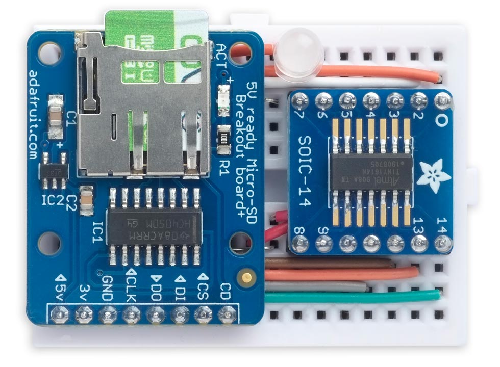
An I2C SD-Card Module that allows you to write to and read from SD cards via I2C.
It's based on an ATtiny1614 and a few other components, and it's compact enough to fit on a mini-breadboard.
For a PCB version of this project see I2C SD-Card Module PCB.
Update
3rd December 2024: Added a note about SD card compatibility.
8th March 2025: Two users have reported that the SD-card module doesn't work with the I2C interface on an ESP32. I've confirmed this, but haven't yet been able to find a solution, so currently it's not suitable for use with the ESP32.
Introduction
I've frequently had a project where I wanted to write data to an SD card, or read from an SD card, but didn't have enough I/O lines available to wire up the SPI SD card interface, or else the SPI lines were already in use, or else the processor I was using didn't have enough RAM to run the SD library.
The ideal solution seemed to be an SD module with an I2C interface, but despite much searching on the web I couldn't find one, so I decided to build one myself.
I initially thought of basing the circuit on the ATtiny841, like my earlier I2C GPS Module, but I underestimated the amount of RAM needed by the SD library, and the ATtiny814 only provides 512 bytes. I therefore switched to the 1‑series ATtiny1614 which provides 2 Kbytes.
The circuit
Here's the circuit:
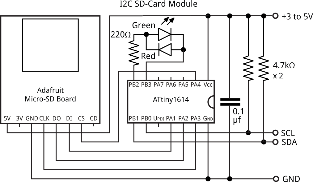
Circuit of the I2C SD-Card Module, based on an ATtiny1614.
For the SD card interface I used the Adafruit MicroSD board [1] as it's easy to use on a breadboard, and it includes a logic-level shifter so you can use it with 3.3V or 5V.
For the controller I used an ATtiny1614. The SD library uses a lot of RAM so you need about 830 bytes, and the ATtiny804 or ATtiny814 aren't suitable as they only have 512 bytes. I also tried an ATtiny1604, but that didn't work, presumably because the 1 Kbytes of RAM doesn't leave enough room for the stack. I'm pretty sure an ATtiny1624 should work, but I haven't tried it.
I mounted the chip on a SOIC-14 breakout board [2] to make it breadboard friendly.
I connected a bicolour red/green LED [3] to two spare I/O lines, PB2 and PB3, to allow me to show errors (red) and when the SD card is being read or written (green). Alternatively you could use two separate LEDs.
The SD card module includes a CD pin which is connected to GND when a card is not inserted. You could connect this to a spare I/O line defined with INPUT_PULLUP to allow you to detect when a card is present.
The whole circuit fitted on a mini breadboard. To use it just connect it to your 3.3V or 5V microcontroller via the following pins:
- VCC (pin 1 on the ATtiny1641).
- GND (pin 14 on the ATtiny1641).
- SDA (pin 8 on the ATtiny1641).
- SCL (pin 9 on the ATtiny1641).
It's a useful module to have lying around, so I plan to design a PCB for it; if I do I'll publish it here.
SD card compatibility
Note that the Arduino SD Card library only supports FAT16 or FAT32; FAT12 and ExFAT are not supported. Although 64 GB or 128 GB cards can be formatted as FAT32, some formatting programs such as File Explorer will only format them in ExFAT. If you have problems using a card check its format.
How it works
I2C address
The I2C address is 0x55, but if this clashes with anything else you're using you can easily change it in the program.
Commands
Each I2C transaction is prefixed by a command byte, to indicate what function is being performed. To make it easy to remember them I made each command a single letter representing its action:
| Command | Name | Description |
| 'F' | Filename | Specifies the filename. |
| 'W' | Write data | Writes data to the file, overwriting if necessary. |
| 'A' | Append data | Appends data to the end of the file, if it already exists. |
| 'R' | Read data | Reads data from the file. |
| 'S' | Size | Gets the size of the open file. |
The Size command can be called before reading a file if you don't know its size.
There is no need to explicitly close the file when you're finished; it is closed automatically after the last transmission.
You can use the I2C SD-Card Module with the Arduino Wire library, but it works best with my TinyI2C library; see Tiny I2C Routines for all AVR Microcontrollers. I give some examples in the following sections. Using TinyI2C it took 15 seconds to save the raw image from a 240x240 TFT display, consisting of 115200 bytes, to an SD Card. Reading it back to the display took 10 seconds.
I tested these examples with the I2C SD-Card Module connected to an Arduino Uno:
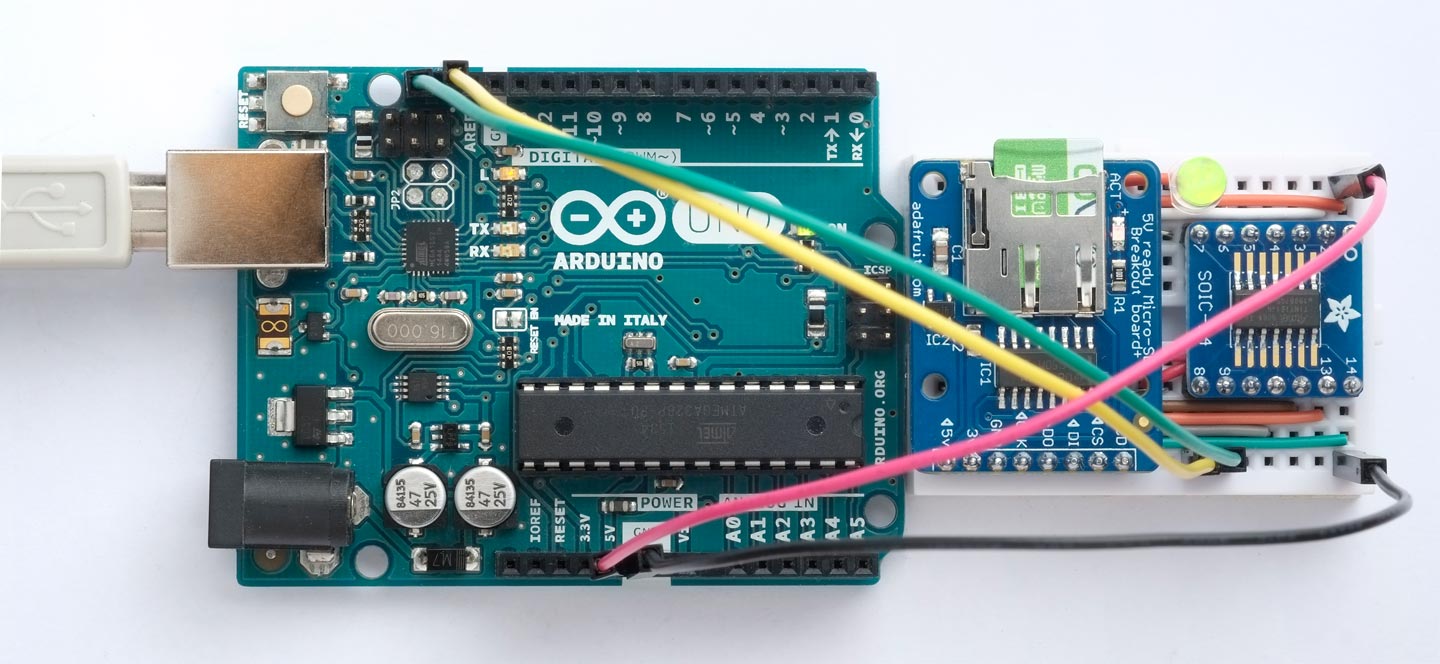
Testing the I2C SD-Card Module with an Arduino Uno.
Using TinyI2C
To run these examples your file should include the following lines:
#include <TinyI2CMaster.h>
int address = 0x55;

void setup (void) {
  Serial.begin(9600);
  TinyI2C.init();
}
Writing to a file
The following example writes the bytes 48 to 90 (ASCII characters '0' to 'Z') to the file "A1":
  Serial.println("Writing...");
  TinyI2C.start(address, 0);
  TinyI2C.write('F');
  TinyI2C.write('A');
  TinyI2C.write('1');
  TinyI2C.restart(address, 0);
  TinyI2C.write('W');
  for (int i=48; i<=90; i++) TinyI2C.write(i);
  TinyI2C.stop();
Reading from a file
The following example reads the 43 characters we wrote to the file in the previous example, and prints them out using Serial.print().
The I2C protocol doesn't provide a way of signalling to the Host that the Client has no more data to send, so we need to get the size of the file before reading it:
  Serial.println("Reading...");
  TinyI2C.start(address, 0);
  TinyI2C.write('F');
  TinyI2C.write('A');
  TinyI2C.write('1');
  TinyI2C.restart(address, 0);
  TinyI2C.write('S');
  TinyI2C.restart(address, 4);
  int size = 0;
  for (int i=0; i<4; i++) size = size<<8 | TinyI2C.read();
  TinyI2C.restart(address, 0);
  TinyI2C.write('R');
  TinyI2C.restart(address, size);
  for (int i=0; i<size; i++) Serial.print((char)TinyI2C.read());
  TinyI2C.stop();
If you knew the size of the file you could leave out the 'S' command and the following four statements.
Specifying a longer filename
The following example shows a more elegant way of specifying the filename in the 'F' command:
  TinyI2C.write('F');
  const char name[] = "DOCUMENT.TXT";
  for (int p=0; name[p]; p++) TinyI2C.write(name[p]);
Using Arduino Wire
To run these examples your file should include the following lines:
#include <Wire.h>
int address = 0x55;

void setup (void) {
  Serial.begin(9600);
  Wire.begin();
}
Writing to a file
The following example writes the bytes 48 to 90 (ASCII characters '0' to 'Z') to the file "A1". Arduino Wire uses a 32-byte buffer, so you have to divide up what you're writing into sections of not more than 32 bytes:
  Serial.println("Writing...");
  Wire.beginTransmission(address);
  Wire.write('F');
  Wire.write('A');
  Wire.write('1');
  Wire.endTransmission(false);
  Wire.beginTransmission(address);
  Wire.write('W');
  for (int i=48; i<79; i++) Wire.write(i);
  Wire.endTransmission(false);
  Wire.beginTransmission(address);
  Wire.write('W');
  for (int i=79; i<91; i++) Wire.write(i);
  Wire.endTransmission();
Reading from a file
The following example reads the 43 characters we wrote to the file in the previous example, and prints them out using Serial.print(). Again, Arduino Wire uses a 32-byte buffer so we have to divide up what we are reading into 32-byte sections:
  Serial.println("Reading...");
  Wire.beginTransmission(address);
  Wire.write('F');
  Wire.write('A');
  Wire.write('1');
  Wire.endTransmission();
  Wire.beginTransmission(address);
  Wire.write('S');
  Wire.endTransmission(false);
  Wire.requestFrom(address, 4, false);
  unsigned long size = 0;
  for (int i=0; i<4; i++) size = size<<8 | Wire.read();
  Wire.beginTransmission(address);
  Wire.write('R');
  Wire.endTransmission(false);
  while (size > 32) {
    Wire.requestFrom(address, 32, false);
    for (int i=0; i<32; i++) Serial.print((char)Wire.read());
    size = size - 32;
  }
  Wire.requestFrom(address, size, true);
  for (int i=0; i<size; i++) Serial.print((char)Wire.read());
Again, if you knew the size of the file you could leave out the 'S' command and the following four statements.
The program
Implementing this project was an interesting exercise in getting to understand the TWI peripheral in the new AVR processors.
While reading Microchip's latest datasheets [4] I noticed that they've changed their terminology to Host (rather than Master), and Client (rather than Slave), so I'll adopt the new terminology. However, the Host registers still have an "M" prefix, and the Client registers have an "S" prefix, so you need to keep both terminologies in mind!
In this application the I2C SD-Card Module is the Client, and the microcontroller that's accessing it via I2C is the Host.
The most recent AVR microcontrollers have a fairly advanced TWI (Two-Wire Interface) peripheral that provides both Host and Client support, and does a lot of the work for you. In this application I'm using the Client interface in the ATtiny1614. It has one instance of the TWI peripheral, so the registers are all prefixed TWI0.
I found that the key to understanding the I2C protocol is this diagram from page 347 of the ATtiny3224/6/7 datasheet [5]:
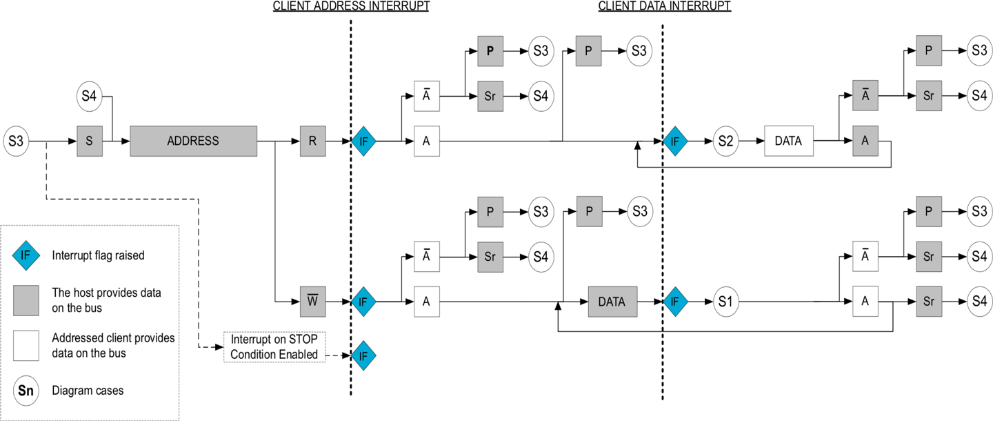
This shows that the key actions you have to perform as the Client are:
- On an address interrupt, when the Host is reading or writing, send an ACK.
- On a data interrupt, when the Host is reading, send data (but no ACK/NACK).
- On a data interrupt, when the Host is writing, read the data and send an ACK or NACK.
There's one inaccuracy in this diagram that misled me until I figured it out: a Client data interrupt is generated after the Client has sent each byte of data, even the last one which the Host responds to with a NACK. On each Client data interrupt you therefore need to check if the Host responded with a NACK by reading the RXACK bit, and not send a byte in this last case.
To keep the code as simple as possible I haven't incorporated much error checking, so if you plan to use the project in a critical application on the same I2C bus as other devices you should probably add this. I'd also welcome any suggestions for improvements.
Initialising I2C
Many of the I2C operations are handled automatically by the peripheral. For example, to make the Client appear on the I2C bus with a particular address you just put the address into the TWI0.SADDR register. The only other thing you need to do is to tell the TWI to generate an interrupt on address, data, and stop events, and enable it:
const int MyAddress = 0x55;

void I2CSetup () {
  TWI0.CTRLA = 0;                                        // Default timings
  TWI0.SADDR = MyAddress<<1;                             // Bottom bit is R/W bit
  // Enable address, data, and stop interrupts:
  TWI0.SCTRLA = TWI_APIEN_bm | TWI_DIEN_bm | TWI_PIEN_bm | TWI_ENABLE_bm;
}
I2C interrupt handler
The address, data, and stop interrupts are all handled by the same interrupt handler, and this checks the flags TWI_APIF_bm, TWI_AP_bm, and TWI_DIF_bm in the Client status register, TWI0.SSTATUS, to determine what event has caused the interrupt.
In each section we can distinguish between whether the Host is reading or writing by checking the TWI_DIR flag.
To make the interrupt handler easier to understand I have delegated each of the actual actions to separate functions with self-explanatory names. This should make it easier if you want to repurpose this code for your own I2C Client application. Here's the whole interrupt handler:
ISR(TWI0_TWIS_vect) {
  boolean succeed;

  // Address interrupt:
  if ((TWI0.SSTATUS & TWI_APIF_bm) && (TWI0.SSTATUS & TWI_AP_bm)) {
    if (TWI0.SSTATUS & TWI_DIR_bm) {                     // Host reading from client
      succeed = AddressHostRead();
    } else {
      succeed = AddressHostWrite();                      // Host writing to client
    }
    SendResponse(succeed);
    return;
  }

  // Data interrupt:
  if (TWI0.SSTATUS & TWI_DIF_bm) {
    if (TWI0.SSTATUS & TWI_DIR_bm) {                     // Host reading from client
      if ((TWI0.SSTATUS & TWI_RXACK_bm) && checknack) {  // Host responded with NACK
        checknack = false;
      } else {
        DataHostRead();
        checknack = true;
      }
      TWI0.SCTRLB = TWI_SCMD_RESPONSE_gc;                // No ACK/NACK needed
    } else {                                             // Host writing to client
      succeed = DataHostWrite();
      SendResponse(succeed);
    }
    return;
  }

  // Stop interrupt:
  if ((TWI0.SSTATUS & TWI_APIF_bm) && (!(TWI0.SSTATUS & TWI_AP_bm))) {
    Stop();
    TWI0.SCTRLB = TWI_SCMD_COMPTRANS_gc;                 // Complete transaction
    return;
  }
}
The checknack flag is to get around the problem that on the first Host read data interrupt, the Host NACK flag is initially left set from the end of the previous operation.
ACK and NAK
I use a function SendResponse() that sends an ACK or NACK depending on whether its parameter is true or false:
void SendResponse (boolean succeed) {
  if (succeed) {
    TWI0.SCTRLB = TWI_ACKACT_ACK_gc | TWI_SCMD_RESPONSE_gc;     // Send ACK
  } else {
    TWI0.SCTRLB = TWI_ACKACT_NACK_gc | TWI_SCMD_RESPONSE_gc;    // Send NACK
  }
}
Where appropriate, each of the action functions returns true or false to specify whether it should generate an ACK or a NACK respectively. A NAK is sent to indicate an error in the following situations:
- The Host has sent a filename that's more than 12 characters long.
- The Host has started writing to or reading from a file that couldn't be opened.
Address interrupt
The address interrupt occurs when the Host writes an address byte to the I2C bus, and the address matches the Client's address.
Here are the action functions for the I2C SD-Card Module:
boolean AddressHostRead () {
  return true;
}

boolean AddressHostWrite () {
  command = 0; ch = 0; ptr = 0;                          // Reset these on writing
  return true;
}
The only action is to reset the state variables when the Host is writing.
Data interrupt
The data interrupt occurs for each of the subsequent data bytes.
If the Host is reading from the Client it occurs after the Client has acknowledged the address byte, and then again after the Host has then acknowledged each of the Client's data bytes.
If the Host is writing to the Client it occurs after the Host has written each byte to the I2C bus.
Data interrupt - Host reading from Client
In the I2C SD-Card Module the action depends on which command we're currently executing.
If the current command is 'R' we send the next byte from the file.
If the current command is 'S' we send the next byte of the file size:
void DataHostRead () {
  if (command == 'R') {
    TWI0.SDATA = myFile.read();                          // Host read operation
  } else if (command == 'S') {
    if (ptr < 4) {
      if (ptr == 0) Filesize = myFile.size();
      TWI0.SDATA = Filebytes[3-ptr];                     // MSB first
      ptr++;
    } else TWI0.SDATA = 0;                               // Host read too many bytes
  } else TWI0.SDATA = 0;                                 // Read in other situations
}
Data interrupt - Host writing to Client
In the I2C SD-Card Module the action again depends on which command we're currently executing.
If there's no active command the byte received specifies the command, and if it's 'W', 'R', 'A', or 'S' we open the specified file in preparation for the specified action.
If the current command is 'F' the byte received is the next character of the filename.
If the current command is 'W' the byte received is written to the open file:
boolean DataHostWrite () {
  if (command == 0) {                                    // No command in progress
    command = TWI0.SDATA;
    if (!myFile && (command != 'F')) {
      if (command == 'W') {
        myFile = SD.open(Filename, O_RDWR | O_CREAT | O_TRUNC);
      } else if (command == 'R' || command == 'S') {
        myFile = SD.open(Filename, O_READ);
      } else if (command == 'A') {
        myFile = SD.open(Filename, O_RDWR | O_CREAT | O_APPEND);
      }
      if (myFile) {
        LightLED(LEDgreen);                              // File opened successfully
        return true;
      } else {
        LightLED(LEDred);                                // Problem
        return false;
      }
    } else {
      return true;
    }
  } else if (command == 'F') {                           // Read filename
    if (ch < Namelength) {
      Filename[ch++] = TWI0.SDATA;
      Filename[ch] = 0;
      return true;
    } else {                                             // Filename too long
      return false;
    }
  } else if (command == 'W' || command == 'A') {
    myFile.write(TWI0.SDATA);                            // Write byte to file
    return true;
  } else if (command == 'R' || command == 'S') {
    return false;
  }
}
Stop interrupt
The stop interrupt occurs when the Host has generated a stop condition. Note that a stop condition is not generated after a restart; just at the end of the transaction.
In the I2C SD-Card Module we use the stop interrupt to close the file:
void Stop () {
  if (command == 'W' || command == 'R' || command == 'A' || command == 'S') {
    myFile.close(); LightLED(LEDoff);                    // Close file
  }
}
Compiling the I2C SD-Card Module
Compile the program using Spence Konde's megaTiny Core on GitHub. Choose the ATtiny3224/1624/1614/1604/824/814/804/424/414/404/241/204 option under the megaTinyCore heading on the Board menu. Check that the subsequent options are set as follows (ignore any other options):
Chip: "ATtiny1614"
Clock: "20 MHz internal"
Then upload the program to the ATtiny1614 using a UPDI programmer. The recommended option is to use a USB to Serial board, such as the SparkFun FTDI Basic board [6], connected with a 4.7kΩ resistor as follows:
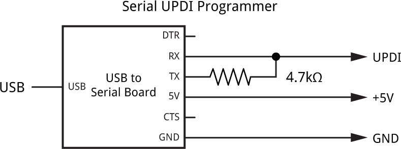
Set the Programmer option to "SerialUPDI with 4.7k resistor or diode (230400 baud)".
Resources
Here's the program for the I2C SD-Card Module: I2C SD-Card Module Program.
Or get it from GitHub here: https://github.com/technoblogy/i2c-sd-card-module.
Here's the test program using TinyI2C: I2C SD-Card Module Test TinyI2C.
and here's the test program using Arduino Wire: I2C SD-Card Module Test Wire.
Further suggestions
In this project I've implemented the essential functionality to read and write files to an SD card, but you could extend it to support the other features of the Arduino SD library [7] including working with directories, seeking to a position within a file, and deleting files.
- ^ MicroSD card breakout board on Adafruit.
- ^ SMT Breakout PCB for SOIC-14 or TSSOP-14 on Adafruit.
- ^ Green & Red LED 5mm on RS Components.
- ^ ATtiny3224/6/7 Datasheet on microchip.com.
- ^ ATtiny3224/6/7 Datasheet on microchip.com.
- ^ SparkFun FTDI Basic Breakout - 5V on Sparkfun.
- ^ SD library reference on Arduino.cc.
blog comments powered by Disqus