Flashing Thermometer
30th January 2016
This article describes a simple thermometer, based on an ATtiny85, that displays the temperature as a series of red and green flashes:
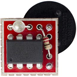
Flashing thermometer, displays the temperature in negabinary on a bi-colour LED.
The thermometer consists of just an ATtiny85 and a bi-colour LED, using the sensor in the ATtiny85 to measure the temperature, and to avoid the need for a digital display the thermometer pulses the temperature as a series of flashes on the bi-colour LED, green for a zero and red for a one. I designed it so I could seal it in a small plastic bag and put it outside the window, allowing me to see the outside temperature from inside.
It incorporates several power-saving features to enable it to run for two years on a pair of 1.5V AAA cells, or half a year on a CR2032 button cell.
For a similar project based on an ATtiny10 see ATtiny10 Thermometer.
Negabinary
The thermometer displays the temperature in a little-known notation called negabinary, which is ideal for this application; if you prefer you could easily modify the program to use a more conventional notation, such as signed binary, or even morse code.
To understand negabinary, first consider how binary represents numbers using the digits 0 and 1. Each bit represents the power of two corresponding to its position; so, for example, the binary number 1101011 represents 107, because 64 + 32 + 8 + 2 + 1 = 107:
Negabinary is similar, except that it uses the powers of -2 rather than the powers of 2. So each bit represents the power of -2 corresponding to its position, and in negabinary the number 1101011 represents 23 because 64 - 32 - 8 - 2 + 1 = 23:
So what's the point of negabinary? Its advantage over binary is that it can represent both positive and negative numbers in a consistent, compact way. This is exactly what we want for temperatures, because the temperatures we are measuring tend to be either side of zero. For example, the lowest recorded temperature in the UK was -27°C (Altnaharra, December 1995), and the highest was 38°C (Kent, August 2003). We can represent both of these in negabinary as follows:
It flashes the digits starting with the most significant negabinary digit, so the first flash will always be red, unless the temperature is zero in which case it gives a single green flash.
Converting from negabinary
There's a very easy way of converting a number from negabinary to decimal. With a bit of practice you can do it in your head as you're reading the flashes from the thermometer:
Keep a running total; initially the total is 0. Then, starting with the most significant digit, repeat this for each digit:
- Multiply your total by -2.
- Add the value of the digit (green=0 or red=1) to your total.
When there are no more digits your total is the decimal value of the number.
The circuit
Here's the circuit of the negabinary thermometer:
Circuit of the flashing thermometer.
For the LED I chose an ultra-bright red/green bicolour LED from Kingbright, which is still clearly visible with a very short pulse duration [1]. Alternatively you could use separate red and green LEDs.
I built the circuit on a tiny prototyping board from Sparkfun with 5x5 holes, but you could use a piece of veroboard, or just solder everything directly together. The button cell holder was mounted on the reverse of the board:
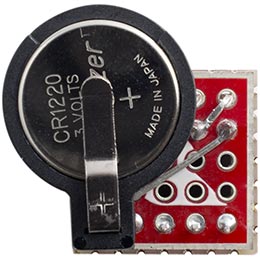
Reverse of the flashing thermometer, showing the button cell holder.
The program
Converting to negabinary
The program uses the following ingenious routine to convert the temperature from a signed integer to an unsigned integer representing the negabinary result:
unsigned int NegaBinary (unsigned int value) {
  return (value + 0xAAAAAAAA) ^ 0xAAAAAAAA;
}
The way this works is quite obscure; there's an explanation in Hacker's Delight [2].
Reading the temperature
All the ATtiny and ATmega chips include a built-in temperature sensor (apart from the ATtiny2313 which doesn't have an analogue-to-digital converter). You read it in same way as reading any of the analogue inputs. For highest accuracy when reading the internal temperature sensor the datasheet recommends using ADC Noise Reduction Mode, so in setup() the ADC is set up to generate an interrupt when the conversion is complete:
  ADMUX = 0<<REFS2 | 2<<REFS0 | 15<<MUX0;  // temperature and 1.1V reference
  ADCSRA = 1<<ADEN | 1<<ADIE | 3<<ADPS0;   // enable ADC, interrupt, 125kHz ADC clock
The ReadADC() routine then puts the processor into ADC Noise Reduction Mode, and reads and returns the result:
int ReadADC() {
  ADCSRA = ADCSRA | 1<<ADEN;               // Enable ADC
  set_sleep_mode(SLEEP_MODE_ADC);
  sleep_enable();
  sleep_cpu();                             // Go into ADC noise reduction mode
  int low, high;                           // Return here on ADC interrupt
  low = ADCL;
  high = ADCH;
  ADCSRA = ADCSRA & ~(1<<ADEN);            // Disable ADC to save power
  return (high<<8 | low);
}
Displaying the number as flashes
Here's the routine to display a binary number as a series of red or green flashes:
void Flash(unsigned int value) {
  int i=9, colour;
  boolean b, show=false;
  do {
    b = value>>i & 1;
    if (show || b || (i==0)) {
      if (value>>i & 1) colour = red; else colour = green;
      digitalWrite(colour, HIGH);
      WDDelay(0);                              // 12msec flash
      digitalWrite(colour, LOW);
      WDDelay(6);                              // 1 second gap
      show = true;
    }
    i--;
  } while (i>=0);
}
It uses the variable show to suppress leading zeroes unless the number is zero, in which case it gives a single green flash.
Calibration
The value produced by the internal temperature sensor is
v = a ⋅ t + k
where v is the digital value from 0 to 1023, t is the temperature in degrees Celsius, and a and k are constants which depend of the temperature sensor in your particular ATtiny85 chip. To calibrate the thermometer you need to read the digital value from the internal temperature sensor v1 and v2 at two known temperatures t1 and t2, and then find a and k using the following equations:
a = (t2 - t1)/(v2 - v1)
k = t1 - a ⋅ v1
To do this, compile the program with loop() changed to:
void loop() {
  int Temperature;
  // Go to sleep to save power until the watchdog timer wakes us up
  WDDelay(9);                              // 8 second delay
  WDDelay(9);                              // Another 8 second delay
  Temperature = ReadADC();                 // Raw ADC value
  Flash(Temperature);
}
This will display the digital value in binary as a series of up to 10 flashes. I measured the temperature outside on a frosty evening, and inside in a centrally-heated house, and calculated the values as follows:
a = 0.94
k = -267.8
A good approximation to 0.94 is 31/33, and 267.8*33 is 8837, so to convert the ADC value to degrees Celsius and flash the temperature in negabinary I used:
  Temperature = (ReadADC()*31 - 8837)/33;  // In degrees Celsius
  Flash(NegaBinary(Temperature));
Power saving features
The thermometer uses the following features, in order of importance, to reduce the power consumption and ensure that it will last as long as possible on a single battery.
LED flashes
Most of the power is consumed by the LEDs. I chose a high brightness two-colour LED so it would be visible even with very short pulse durations. It's only on for 12msec, but is still clearly visible.
Power down
Whenever the thermometer is not measuring or displaying the temperature it puts the ATtiny85 to sleep, reducing the power consumption to 0.2µA. The processor sleeps for 16 seconds between each display of temperature, for 1 second between each flash, and for 12msec during each flash. In each case the processor is woken from sleep using the watchdog timer, which generates a watchdog timer interrupt after a specified delay.
Here's the routine to use the watchdog timer for a delay:
void WDDelay(int n) {
  set_sleep_mode(SLEEP_MODE_PWR_DOWN);
  WDTCR = 1<<WDIE | (n & 0x8)<<2 | 1<<WDE | (n & 0x7);
  sleep_enable();
  sleep_cpu();
}
This enables the watchdog timer, and the parameter n sets the watchdog timer prescaler. A value of 0 gives a 16 millisecond delay, and a value of 9 gives an 8 second delay.
The watchdog interrupt service routine simply disables the watchdog timer:
ISR(WDT_vect) {
  // Special sequence to disable watchdog timer
  WDTCR = 1<<WDCE | 1<<WDE;
  WDTCR = 0;
}
Turning off the ADC
Apart from when it is actually being used to measure the temperature, the ADC is turned off to reduce power:
ADCSRA = ADCSRA & ~(1<<ADEN);
Turning off unused modules
The thermometer doesn't use either of the Timer/Counters or the USI, so these are all turned off to avoid using their power:
PRR = 1<<PRTIM1 | 1<<PRTIM0 | 1<<PRUSI;
These features combine to reduce the average power consumption to 0.05mA, which is equivalent to about 180 days for a CR2032 button cell with a capacity of 225mAH.
I also tried reducing the processor speed, using the system clock prescaler, but this had a negligible effect on the power, presumably because the processor spends most of the time asleep.
Compiling the program
I compiled the program using Spence Konde's ATTiny Core [3]. Choose the ATtiny25/45/85 option under the ATtinyCore heading on the Board menu. Then choose Timer 1 Clock: CPU, B.O.D. Disabled, ATtiny85, 1 MHz (internal) from the subsequent menus. Choose Burn Bootloader to set the fuses appropriately. Then upload the program using ISP (in-system programming); I used Sparkfun's Tiny AVR Programmer Board; see ATtiny-Based Beginner's Kit.
Here's the whole Flashing Thermometer program: Flashing Thermometer Program.
Update
7th January 2019: I've updated the description to recommend using Spence Konde's ATTiny Core, and I've added an explanation of the order in which the digits are flashed.
- ^ Kingbright L-93WSURKCGKC LED on Farnell.
- ^ Warren Jr., Henry S. (2013) [2002]. Hacker's Delight (2 ed.). Addison Wesley - Pearson Education, Inc., p. 305-306.
- ^ ATTinyCore on GitHub.
blog comments powered by Disqus