ATtiny10 POV Pendant
19th May 2018
This article describes a miniature pendant based on the ATtiny10. It features an RGB LED that pulsates white slowly on and off. When you move, the white light turns into a band containing red, green, blue, cyan, magenta, and yellow stripes.
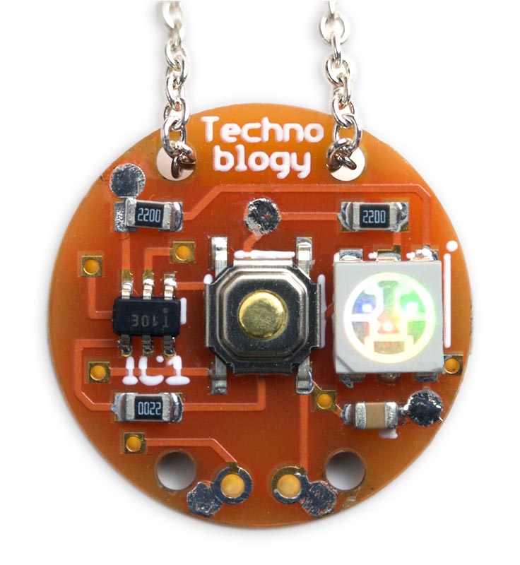
POV Pendant based on an ATtiny10.
The ATtiny10 has three I/O pins, just enough to drive an RGB LED. To turn the display on a pushbutton resets the processor. Alternatively you can use a vibration sensor to turn the pendant on, so it lights up automatically when you move. I've made provision for either option on the circuit board.
To avoid the need for an on/off switch the ATtiny10 is put to sleep after the display has been on for a minute. The current consumption in sleep mode is under 0.1µA, which will give negligible battery consumption when the pendant isn't being used.
How it works
The POV Pendant works as follows. The RGB LED flashes between red, green, blue, cyan, magenta, and yellow at about 250Hz, which is just fast enough so that the eye's persistence of vision (POV) merges the colours into a continuous white spot. However, if you move the pendant, such as when cycling down the street, running, or dancing in a club, the eye sees a band of light separated into coloured strips.
The circuit
Here's the circuit of the ATtiny10 Pendant:
Circuit of the ATtiny10-based POV Pendant.
Construction
I built a prototype on a mini breadboard using through-hole components to test out the circuit:
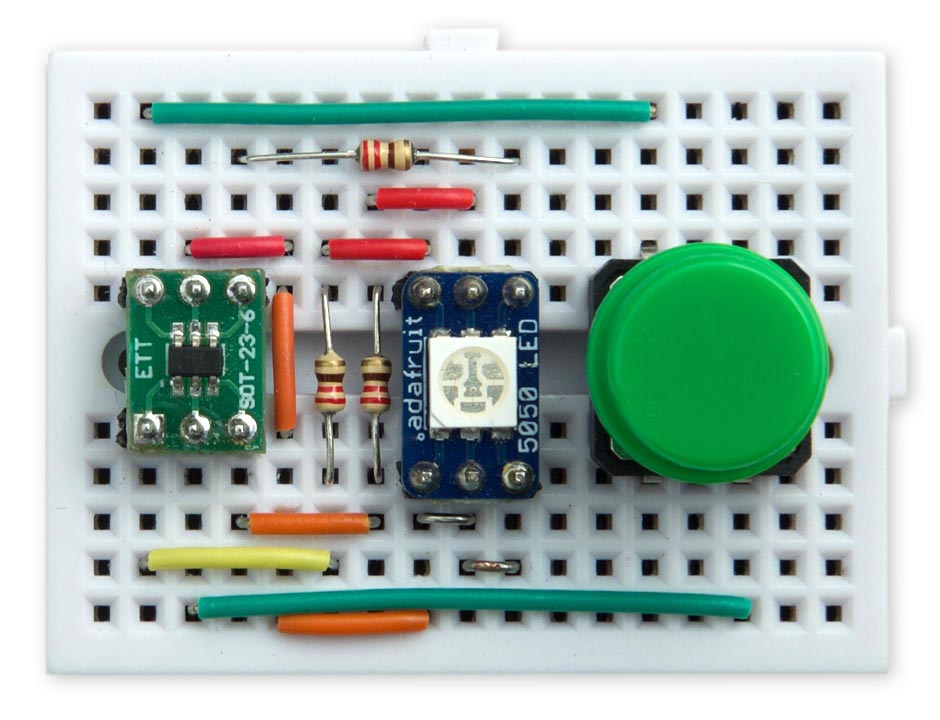
Prototype of the ATtiny10-based POV Pendant.
For the final version I designed a board in Eagle and sent it to Ragworm in the UK for fabrication. Here's the preview from OSH Park:
The front and back of the ATtiny10 POV Pendant circuit board.
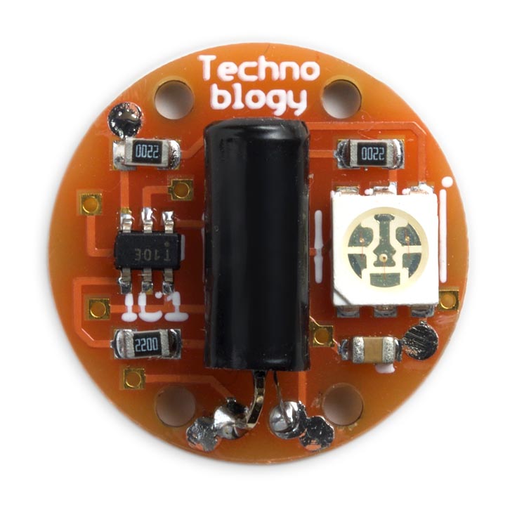
I used an ATtiny10 in an SOT-23 package, and 0805 resistors and capacitors. It should be possible to solder all the components by hand, using a fine-tipped soldering iron, but I used a Youyue 858D+ hot air gun set to 250°C.
The LED is an SMD RGB 5050 device, available from a variety of suppliers such as Adafruit [1]. Note that the chamfer on the package marks pin 4, not pin 1 as you'd expect; I was caught out by this initially.
The button is the same as I've used on several of my projects, a miniature SMD push button available from Sparkfun [2], or Proto-PIC in the UK [3]. Alternatively, instead of a pushbutton you can use a vibration sensor switch, such as the one available from Adafruit [4]:
Alternative version of the POV Pendant incorporating a vibration sensor.
The pendant is designed to work with a 3V 12mm coin cell; types 1216, 1220, or 1225 are suitable. The battery fits in an SMD 12mm coin cell holder [5].
Once all the SMD components were soldered on the front of the board I finally soldered the battery holder onto the back of the board using a conventional soldering iron. Note that the +VE power supply circuit is completed by the battery clip on the rear of the board, so you need to solder this in place before you can program the ATtiny10.
The program
The program uses the ATtiny10's 16-bit Timer/Counter to generate interrupts, which are used to switch on and off the appropriate LEDs.
The ATtiny10 only has 32 bytes of RAM for variables, and this is also used for the stack when entering an interrupt service routine, so it is quite easy to inadvertently use up too much RAM with variables and cause the program to misbehave. In an earlier version of the program I used an array to store the sequence of colours, and this stubbornly refused to work. I eventually tracked down the problem to the lack of RAM.
The LED is flashed by interrupts, generated by the ATtiny10's 16-bit Timer/Counter0. The first part of the program sets this up in Mode 14, a Fast PWM mode with the maximum count defined by ICR0, and OCR0A used to generate a compare match:
 TCCR0A = 2<<WGM00;             // No outputs, fast PWM, Top=ICR0
 TCCR0B = 3<<WGM02 | 1<<CS00;   // Divide clock by 1
 ICR0 = 4095;
 OCR0A = 1;
 TIMSK0 = 1<<OCIE0A | 1<<TOIE0; // OVF and COMPA interrupts
The COMPA and Overflow interrupts are enabled. The 1MHz system clock is divided by 1, so the interrupt frequency is 1000000/4096 which is about 244Hz. I chose this value because it's just fast enough to avoid flicker when switching between 6 colours.
The Overflow interrupt service routine is called when the counter reaches 4095. This sets Output to the next colour, and outputs it to the three I/O lines on PORTB:
ISR(TIM0_OVF_vect) {
  Output = (Output+1) % Colours;
  PORTB = Output+1;
}
Output counts from 0 to 5, so Output+1 counts from 0 to 6, which conveniently gives every combination of the I/O lines apart from all off or all on, thus stepping through the alternative colours available on the RGB LED, excluding white.
When the counter matches the value in OCR0A the COMPA interrupt service routine turns all the LEDs off:
ISR(TIM0_COMPA_vect) {
  PORTB = 0xFF;
}
This allows us to adjust the brightness of the LEDs. When OCR0A is 0 the LEDs are turned off almost immediately after they are turned on by the Overflow interrupt service routine, and the brightness in at its minimum. When OCR0A is close to the top value of the counter, 4095, the LEDs are on all the time, and the brightness is at a maximum.
Two for loops ramp up the brightness of the LEDs, and then ramp it down again:
   for (int b=0; b<=4050; b++) {
    OCR0A = b;
    delay(2);
   }
   for (int b=4050; b>=0; b--) {
    OCR0A = b;
    delay(2);
   }
The calls to a delay() routine allow you to adjust the speed of the pulsating brightness.
Finally, when the LEDs have gone through one cycle the processor is put into power-down sleep mode. Pressing the reset button wakes the processor from sleep and repeats the cycle.
At its brightest the circuit takes about 4mA from the battery. When asleep the circuit takes 20nA, which should give an almost unlimited battery life.
Compiling the program
I compiled the program using the ATtiny10Core hardware configuration which you can download from my ATtiny10Core repository on GitHub. Select the ATtiny10/9/5/4 option under the ATtiny10Core heading on the Boards menu. Then choose ATtiny10 from the Chip menu.
I uploaded the program to the board using the USBasp programmer. For more details about the procedure see my earlier article Programming the ATtiny10 [Updated].
I provided five circular pads on the circuit board to give access to the ATtiny10 pins you need to connect to when uploading a program. I temporarily soldered wires to these pads, and removed them when I had programmed the circuit. Alternatively you could make yourself a jig using pogo pins:
Connections on the POV Pendant for programming the ATtiny10.
Here's the whole ATtiny10 POV Pendant program: ATtiny10 POV Pendant Program.
Alternatively, get it on GitHub here together with the Eagle files for the PCB: ATtiny10 POV Pendant on GitHub.
Or order a board from OSH Park here: ATtiny10 POV Pendant Board.
Update
7th March 2021: Updated the program for compatibility with the latest version of my ATtiny10Core.
- ^ SMT RGB 5050 LED 10 pack on Adafruit.
- ^ Mini Push Button Switch - SMD on SparkFun.
- ^ Mini Push Button Switch (SMD) on Proto-PIC.
- ^ Medium Vibration Sensor Switch on Adafruit.
- ^ Coin Cell Battery Holder - 10mm (SMD) on Farnell.
blog comments powered by Disqus