Driving LED Displays with Fewer I/O Lines
24th September 2015
Many microprocessor projects involve displaying a numerical result; these include clocks, counters, meters, games, and many other applications. Although you can buy a serial display module that you can drive using a serial protocol, the cheapest and most flexible way to provide a numeric display is by driving seven-segment LED displays directly from the I/O lines of the microprocessor.
In this article I show how you can use a technique that has become known as "charlieplexing" to drive different combinations of multiple LED seven-segment display modules using the minimum number of I/O lines. It's illustrated with the practical application of driving two 4-digit displays using just 12 I/O lines from an ATtiny2313:
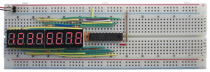
Driving an 8-digit seven-segment display from an ATtiny2313 using charlieplexing.
Charlieplexing
At first sight you'd think you need n+7 I/O lines to drive n 7-segment LED displays, or n+8 if you want to include decimal points. However, by taking advantage of the fact that LEDs only conduct current in one direction, and you can program the I/O lines to be high, low, or high-impedance, you can actually do better than this when driving more than one LED display module; this technique is known as charlieplexing.
The best way to plan a circuit using charlieplexing is to draw a matrix representing the state that each of the I/O lines can take; anodes (ie +5V) along the top, and cathodes (ie ground) down the side. Each cell represents a position where we can connect an LED. The dark grey squares down the diagonal represent impossible positions, since an I/O line cannot be both an anode and a cathode at the same time.
Each seven-segment display package is constrained by the fact that the anodes and cathodes are commoned within each package, so they have to be represented by a rectangular block within the white squares on the matrix. If you're using common-anode displays the segments within one display digit share the same anode, so they will be represented as a vertical column of cells on these diagrams. In all but the last of the following diagrams I assume all the displays are common anode; if you're using common-cathode displays just switch the labels "Anodes" and "Cathodes".
Example
Let's start by looking at the simple example of using two 2-digit display modules. The standard way of wiring these is represented by the following diagram, which uses 11 I/O lines:
The first module contains digits 1 and 2, and the second module contains digits 3 and 4. I/O lines 1 to 4 connect to the common anodes of each display. I/O lines 5 to 11 connect to the commoned segments in both modules. For example, to light up a minus sign on display 1 (segment G) we need to take I/O line 1 high and I/O line 5 low.
When you're implementing this diagram in an actual circuit you can choose any convenient assignment of I/O pins to the numbered rows and columns on the matrix. For example, assigning numbers 5 to 11 to pins PA0 to PA6 would allow you to write the data to display a single seven-segment character in a single operation.
Using charlieplexing we can alternatively wire up these two 2-digit display modules like this:
By using some of the I/O lines for dual purposes we can reduce the number of I/O lines we need by 2.
For example, to light up a minus sign on display 1 (segment G) we need to take I/O line 1 high and I/O line 5 low. To light up a digit "1" on display 3 (segments A and B) we take line 8 high and lines 1 and 2 low.
The order of segments and digits is arbitrary. Here I've arranged it so segments C to G can be written to lines 3 to 7 in a single operation, to make the programming easier.
When wiring up the displays don't forget to include current-limiting resistors; the easiest place is between each digit and the appropriate I/O pin, so you will need one resistor per digit.
The following diagrams show how to wire up some typical display combinations, using charlieplexing to minimise the number of I/O lines required.
Four display digits
Two 2-digit displays, 7 segments. 9 I/O lines (saving 2):
Two 2-digit displays, 7 segments plus DP. 10 I/O lines (saving 2):
Six display digits
Two 3-digit displays, 7 segments. 10 I/O lines (saving 3):
Two 3-digit displays, 7 segments plus DP. 11 I/O lines (saving 3):
Eight display digits
Two 4-digit displays, 7 segments. 11 I/O lines (saving 4):
Two 4-digit displays, 7 segments plus DP. 12 I/O lines (saving 4):
For a practical example of this configuration, see below.
12 display digits
Finally, if you can get hold of matching common-cathode and common-anode displays, here's a neat trick that drives two 3-digit common-cathode and two 3-digit common-anode displays, 7 segments, with just 13 I/O lines (saving 6):
An example
Finally, as an example, here is the circuit and corresponding program to drive two 4-digit seven-segment LED displays, with decimal points, using an ATtiny2313. I designed this circuit as the display section of a larger project that I hope to describe in a future article.
The standard way of connecting to these displays would use 8 lines for the segments, and 8 lines for the digits, making a total of 16. However, the ATtiny2313 only has 17 available I/O lines, so that only leaves one line; not enough for a typical application, such as interfacing to an SPI device. Using the techniques described in this article we can reduce the requirement to 12 I/O pins, leaving five I/O lines spare.
Here's the matrix diagram showing the assignment of lines to the I/O pins. I've assigned segments G to D to pins PD0 to PD3, to make it easy to write those four bits in a single operation; likewise, segments C to A are assigned to PB0 to PB2 or PD4 to PD6. The DP can be assigned to any pin, since it is handled as a special case:
I purposely left PB5 to PB7 free as these are dedicated to the USI, which I thought I would need in my application.
The circuit
Here's the complete circuit:
Circuit to drive an 8-digit seven-segment display from an ATtiny2313 using charlieplexing.
Four-digit display modules are available from a variety of suppliers; I got mine from eBay.
Multiplexing the display
As in some of my previous projects, the display is generated under interrupt, using the contents of the array Buffer[]. For example, to display "87654321" execute:
Buffer[0]=8; Buffer[1]=7; Buffer[2]=6; Buffer[3]=5;
Buffer[4]=4; Buffer[5]=3; Buffer[6]=2; Buffer[7]=1;
Timer/Counter1 is configured in setup() to generate an interrupt at 500Hz, which is used to multiplex the display:
  TCCR1A = 0<<WGM10;
  TCCR1B = 1<<WGM12 | 1<<CS10;  // Divide by 1
  OCR1A = 1999;                 // Compare match at 500Hz
  TIMSK |= 1<<OCIE1A;           // Compare match interrupt enable
With an interrupt of 500Hz each display flashes at 62.5Hz, which is safely above the frequency at which flicker would be noticable.
The compare match interrupt service routine then simply calls DisplayNextDigit():
ISR (TIMER1_COMPA_vect) {
  DisplayNextDigit();
}
This reads the data in the appropriate element of Buffer[] and lights the segments in the corresponding display digit:
void DisplayNextDigit() {
  pinMode(Digits[digit], INPUT);
  digit = (digit+1) % 8;
  // Make all segment pins high-impedance inputs
  DDRD = 0;         // PD6 to PD0
  DDRB &= 0xF0;     // PB3 to PB0
  DDRA &= 0xFE;     // PA0
  int segs = charArray[Buffer[digit]];
  // Take lit segments low and make them outputs.
  // Segments D to G go to PD3 to PD0
  // Top three segments A to C go to PB2 to PB0 or PD6 to PD4
  if (digit < 4) {
    PORTB = (PORTB & 0xF8) | ~((segs & 0x70)>>4);
    DDRB = (DDRB & 0xF8) | ((segs & 0x70)>>4);
    PORTD = ~(segs & 0x0F);
    DDRD = (segs & 0x0F);
  } else {
    PORTD = ~(segs & 0x7F);
    DDRD = (segs & 0x7F);
  }
  // Decimal point goes to PB3 or PA0
  if (dp == digit) {
    if (digit < 4) { digitalWrite(PIN_B3,LOW); pinMode(PIN_B3,OUTPUT); }
    else { digitalWrite(PIN_A0,LOW); pinMode(PIN_A0,OUTPUT); }
  }
  // Take current digit pin high
  digitalWrite(Digits[digit],HIGH);
  pinMode(Digits[digit],OUTPUT);
}
This routine is slightly more complicated than in single-display applications, because it has to handle each display module differently to take account of the charlieplexing. For convenience I use the Arduino routines digitalWrite and pinMode when I need to change a single I/O bit, but I write to the PORTx and DDRx registers when I'm changing several bits at once.
I also include a routine to convert a long integer to the appropriate eight-digit decimal number in Buffer[], with leading-zero suppression:
void Display (long number) {
  boolean dig = false;
  long j=10000000;
  for (int d=0; d<8 ; d++) {
    int i = (number/j) % 10;
    if (!i && !dig && d<7) Buffer[d]=Space;
    else { Buffer[d]=i; dig = true; }
    j=j/10;
  }
}
The demo program uses this to count up, starting from 12345678, once per second.
I compiled the program using the Arduino-Tiny core extension to the Arduino IDE [1] using the ATtiny2313 @ 1 MHz option on the Board submenu. This is the default configuration of the ATtiny2313 so the fuse settings don't need to be changed. I uploaded the program to the ATtiny2313 using Sparkfun's Tiny AVR Programmer [2] (available in the UK from Proto-PIC [3]).
Here's the whole Eight-Digit Display Demo program: Eight-Digit Display Demo Program.
- ^ Arduino-Tiny core on Google Code.
- ^ Tiny AVR Programmer on Sparkfun.
- ^ Tiny AVR Programmer on Proto-PIC.
blog comments powered by Disqus