Adjustable Load
24th March 2016
This article describes an adjustable load which provides a constant-current load for testing power supplies, batteries, and LEDs. It allows you to set the load current to any value, up to 1A, using a potentiometer, and displays the current on a three-digit LED display controlled by an ATtiny84:
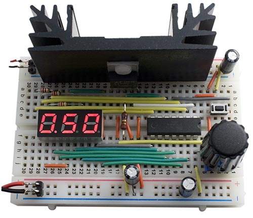
Adjustable load, provides a constant current load of up to 1A for testing power supplies
and rechargeable batteries.
As well as testing power supplies, the adjustable load can be used for testing rechargable NiMH and Lithium-Ion batteries under different load conditions. It measures the current over time, and displays the battery's capacity in mAh or Ah. This is useful for comparing different makes of battery, or for deciding whether a battery has reached the end of its life.
The circuit
Here's the full circuit of the adjustable load:
Circuit of the adjustable load.
The constant-current circuit is based on an LT3080 regulator [1]. This uses a current reference of 10µA, rather than a voltage reference like regulators such as the LM317, and will operate down to 1.5V and 1mA.
The current is sensed by a 1Ω resistor, and this is fed to the sense input of the regulator, via a 100kΩ potentiometer. Since the current through the potentiometer is 10µA, at its maximum setting the voltage across it will be 1V, so the output of the regulator will be maintained at 1V across the 1Ω resistor, producing a constant current of 1A.
The LT3080 is available in a few different packages. I chose the TO220-5 package which provides a separate VCONTROL pin, and is convenient to mount on a prototyping board. To do this I splayed the leads apart to a 0.1" pitch, using a pair of long-nosed pliers. The leads are rectangular, and I also found that I needed to rotate the ends of the leads through 90° before they would fit in the prototyping board:
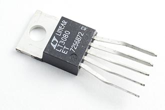
Bending the leads of an LT3080 to fit a prototyping board.
You could power the ATtiny84 and display from the power supply you are testing, via a 3.3V regulator. However, I decided to use a separate 3.7V Lipo battery because this gives two advantages: First, it allows you to test inputs down to as low as 1V. Secondly, it ensures that the microcontroller and display remain powered even when the test supply drops to zero, which is essential for battery testing.
For the LT3080 to regulate, the VCONTROL voltage must be more than 1.2V to 1.35V greater than the output voltage. In some applications this pin can simply be connected to VIN, but here this would limit the minimum voltage that the adjustable load can control to about 2V. The solution is to connect it to the 3.7V supply used to power the ATtiny84 and display.
Displaying the current
The voltage across the 1Ω resistor is read by an analogue input on an ATtiny84, and this then displays it on a three-digit seven-segment display. The analogue input, ADC7 on PA7, is configured in setup() to use the 1.1V reference voltage:
  ADMUX = 2<<REFS0 | 7<<MUX0;          // 1.1V ref, ADC7 (PA7)
  ADCSRA = 1<<ADEN | 4<<ADPS0;         // Enable ADC, 62.5kHz clock
The analogue value is read by the routine ReadADC():
int ReadADC () {
  unsigned char low, high;
  ADCSRA = ADCSRA | 1<<ADSC;           // Start
  do ; while (ADCSRA & 1<<ADSC);       // Wait while conversion in progress
  return ADC;
}
The current is displayed on a three-digit 7-segment display. I used a 0.28" three-digit common anode seven-segment LED display bought on eBay. You could use a common cathode display by changing a few lines in the DisplayNextDigit() routine. Timer/Counter0 multiplexes the display, and this is configured in setup() to generate an interrupt at 312.5Hz:
  TCCR0A = 2<<WGM00;                   // CTC mode
  TCCR0B = 0<<WGM02 | 3<<CS00;         // Divide by 64
  OCR0A = 49;                          // Divide by 50 for 312.5Hz interrupt
  TIMSK0 = 1<<OCIE0A;                  // Enable compare match interrupt
The interrupt service routine simply calls DisplayNextDigit():
ISR(TIM0_COMPA_vect) {
  DisplayNextDigit();
}
This puts the appropriate segment data onto PORTA for the next digit to be displayed, and then takes the digit common line high on PORTB. The number to be displayed on each display digit is specified by the array Buffer[]:
void DisplayNextDigit() {
  static int LastReading;
  DDRB = 0;                                  // Make all digits inputs
  digit = (digit+1) % (Ndigits+1);
  if (digit < Ndigits) {
    char segs = charArray[Buffer[digit]];
    if (digit == DP) {                       // Decimal point
      DDRB = DDRB | 0x04;
      PORTB = PORTB & 0xFB;
    }
    PORTA = ~segs & 0x7F;                    // Mask out PA7 for ADC
    DDRA = segs & 0x7F;
    DDRB = DDRB | 1<<Digits[digit];          // Make digit an output
    PORTB = PORTB | 1<<Digits[digit];        // Take digit bit high
  } else {
    DDRA = 0;                                // All inputs
    PORTA = 0;
    // Read analogue input
    Current = (ReadADC()*13)/14;
    // If current zero, display charge
    if (Current == 0) {
      int mAh = Charge/3600;
      if (mAh < 1000) Display(mAh, -1); else Display(mAh/10, 0);
    } else {
      // Add hysteresis to stop display jumping
      if (abs(LastReading - Current)>=10) {
        Display(Current/10, 0);
        LastReading = Current;
      }
    }
  }
}
Every fourth cycle this routine blanks the display and calls ReadADC() to read the voltage across the 1Ω resistor. Since the ADC is using a 1.1V reference, a reading of 1024 corresponds to 1.1V, so the current in mA is 1024/1100 times the reading. 13/14 is a good approximation to this, and avoids long arithmetic. You can measure the current with a multimeter and then adjust this ratio to compensate for inaccuracies in the value of the 1Ω resistor.
The routine then calls Display() to display the current in amps or, if the current is zero, the charge in Ah or mAh. The routine Display() simply writes the three digits of the value into the array Buffer[].
Calculating battery capacity
The battery capacity feature uses Timer/Counter1 to generate a 1Hz interrupt; this is configured in setup():
  TCCR1A = 0<<WGM10;
  TCCR1B = 1<<WGM12 | 3<<CS10;         // Divide by 64
  OCR1A = 15624;                       // Divide by 15625 for 1Hz interrupt
  TIMSK1 = 1<<OCIE1A;                  // Enable compare match interrupt
The interrupt service routine sums the current every second to calculate the total charge. It also flashes the decimal point to show that the circuit is operating:
ISR(TIM1_COMPA_vect) {
  Charge = Charge + Current;
  if (Current != 0) DP = DP ^ 0xFF;   // Flash decimal point
}
When the current drops to zero, either because the battery is exhausted, or because you have manually turned the current to zero, the meter automatically switches to displaying capacity rather than current. For capacities of up to 999mAh the display shows the number of mAh; otherwise it shows the number of Ah, up to 9.99Ah. To reset the capacity measure press the reset button.
Note that unless otherwise specified, most Lipo batteries have a maximum discharge rate of 2C, which means that the maximum current is twice their rating in mAh; for example, a 100mAh battery has a maximum safe discharge rate of 200mA. By definition, this means that a battery being discharged at this rate should last half an hour.
I used the adjustable load to measure the capacity of a well-used NiMH AAA battery, rated at 1000mAh, after fully recharging it. I set the current to 0.5A:
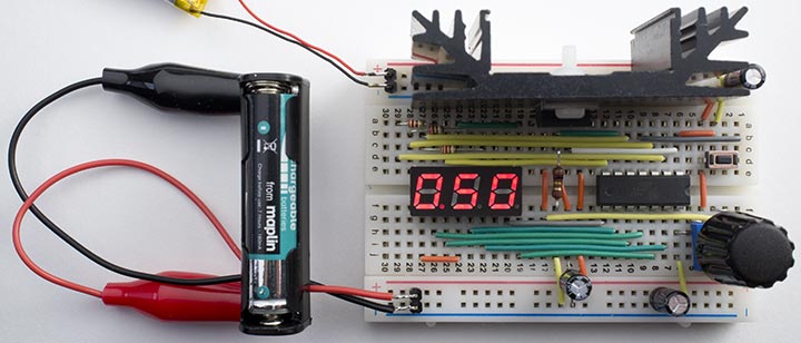
Using the adjustable load to measure the capacity of a rechargeable battery.
When the current dropped to zero the capacity was shown as 650mAh.
The charge calculation relies on the internal oscillator for timing, which is accurate to about 10%. If you want greater accuracy you can calibrate it using the OSCCAL register to within about 1%. Measure the frequency on PB2 with the frequency range of a multimeter, and recompile the program with different values of OSCCAL until the frequency is as close as possible to 156.25Hz.
Construction
I built the circuit on a half-sized prototyping board. The layout was dictated by the heatsink, which is mounted along one edge with the regulator in the centre. The heatsink I used has a thermal rating of 6.8°C/W [2]. With a current of 1A at 5V the voltage across the LT3080 will be 4V, so the power will be 4W; the heatsink will therefore be 27.2°C above the ambient temperature, or typically 47.2°C. This is safely below the recommended maximum operating temperature of 90°C.
Prototyping boards aren't ideal for high currents, so for permanent use the circuit should be transferred to a printed circuit board. Adafruit make a convenient matching circuit board [3].
Compiling the program
I compiled the program using the Arduino-Tiny core extension to the Arduino IDE [4]. Select the ATtiny84 @ 1 MHz (internal oscillator; BOD disabled) option on the Boards menu. This is the default fuse setting on new ATtiny84s; otherwise choose Burn Bootloader to set the fuses appropriately. Then upload the program to the ATtiny84 using the Tiny AVR Programmer Board; see ATtiny-Based Beginner's Kit.
Here's the whole adjustable load program: Adjustable Load Program.
Other options
The LT3080 regulator is rated at up to 36V, so the adjustable load can provide a load of up to 1A at up to 36V, but the regulator will need a larger heatsink for use at higher voltages.
Instead of the LT3080 you could use a standard adjustable regulator, such as the LM317, for the constant current source, but because this uses a voltage reference it will only operate down to 3V.
Another alternative is to use an op-amp and a MOSFET; Dave Jones describes such a circuit in his EEVBlog, using an LM324 and an MTP3055 logic-level MOSFET [5].
Update
25th February 2023: Corrected a mistake in the circuit diagrem.
- ^ LT3080 Datasheet from Linear Technology.
- ^ Aavid Thermalloy 1.25GY50 Heatsink on Farnell.
- ^ Adafruit Perma-Proto Half-sized Breadboard PCB on Adafruit.
- ^ Arduino-Tiny core on Google Code.
- ^ DIY Constant Current Dummy Load in the Electronics Engineering Video Blog, EEVblog.
blog comments powered by Disqus