Push-Button On/Off Switches
22nd May 2015
Every project needs a way of switching on or off the power, and a push-button on/off power switch circuit is often a more convenient option than using a physical toggle switch. It has the added advantage that the circuit can power itself down after a delay, to save power.
I've recently compared three alternative circuits for providing a push-button on/off switch. I tested the circuits by using them to power an ATtiny85 running a simple blink program, which flashes an LED on and off once every 2 seconds.
Finally I present a fourth alternative using just an ATtiny85 processor, with no additional components.
555 timer
The cheapest and simplest circuit uses the ubiquitous 555 timer IC wired as a bistable:
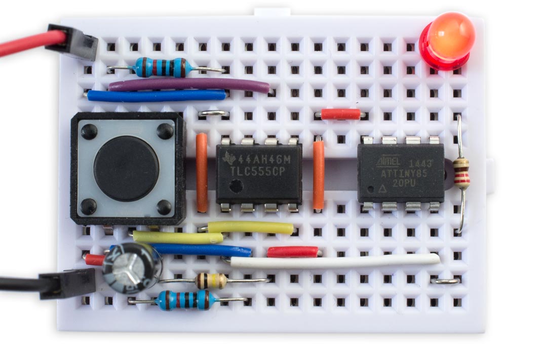
Here's the circuit:
Push-button on/off switch using a 555 timer.
It's using the 555 timer as a Schmitt trigger inverter [1], with the input fed from the output.
I used a CMOS TLC555 which can source 10mA, enough to drive my ATtiny85 blink circuit. For higher currents add a P-channel power MOSFET.
However I can't recommend this circuit because it has a major drawback: it draws a significant current of 350µA in the off state, so your battery will run down even when your circuit is switched off.
Schmitt trigger
The second circuit uses two gates from a CMOS 4093 quad NAND Schmitt trigger package, wired as a bistable:
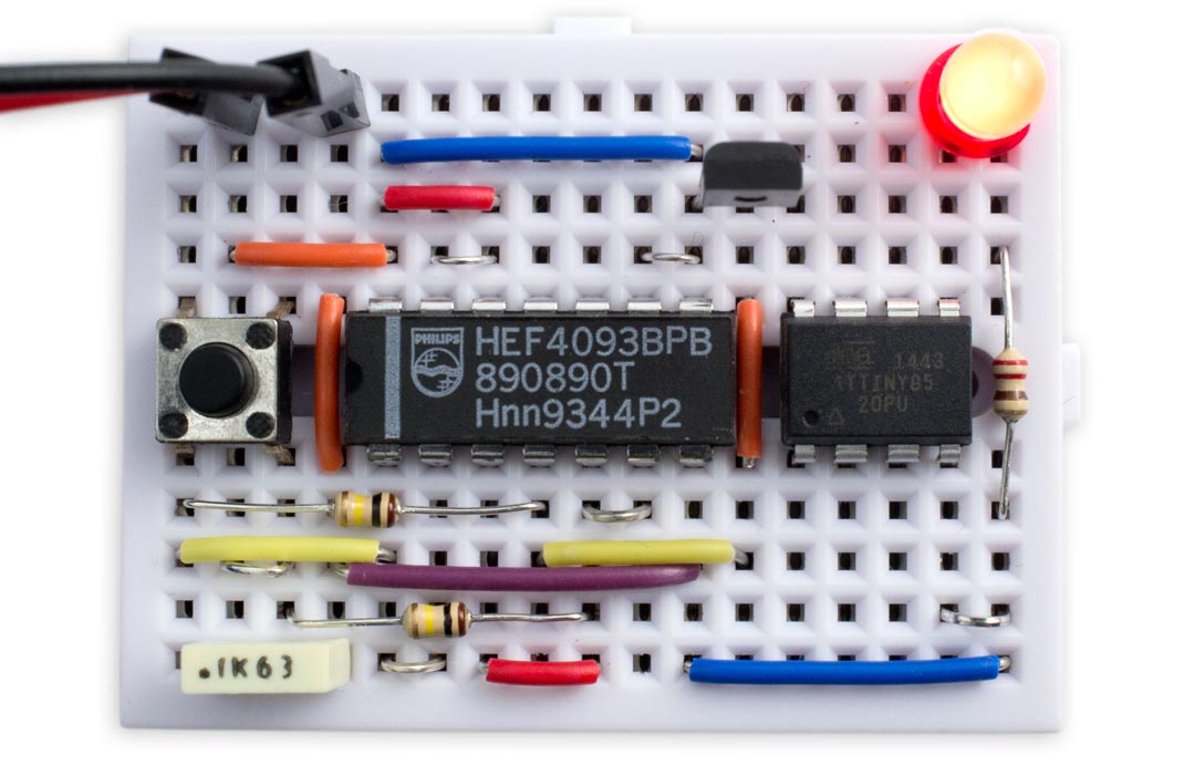
Here's the circuit:
Push-button on/off switch using a CMOS 4093 quad NAND Schmitt trigger package.
Because it uses CMOS gates it only draws current when switching. Note that it's important to tie the inputs of the two unused gates to one power rail; otherwise they oscillate and increase the current consumption. The CMOS gates don't have enough drive capability to drive the ATtiny85 blink circuit directly, under 1mA at 5V, so you need a P-channel MOSFET on the output. To drive more than 100mA use a P-channel power MOSFET, such as the NDP6020P.
This circuit is used by Adafruit for their push-button power switch breakout [2]. On their board an additional transistor provides a 'KILL' input to allow you to turn off the power under control from an external signal.
Complementary MOSFETs
The third push-button on/off switch uses two MOSFETs in a bistable circuit, one P-channel and one N-channel:
Here's the circuit. A third P-channel MOSFET is used to switch on and off the output:
Push-button on/off switch using complementary MOSFETs.
It's taken from the excellent book The Art of Electronics [3], and like the CMOS version it draws no current when the switch is off, because both MOSFETs are in a non-conducting state.
As before, to drive more than 100mA replace the P-channel MOSFET at the output with a power one, such as the NDP6020P.
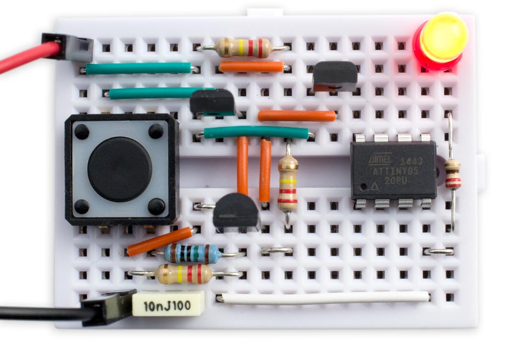
ATtiny version
Finally, an approach that doesn't use any additional components, assuming you've already got a processor in the project:
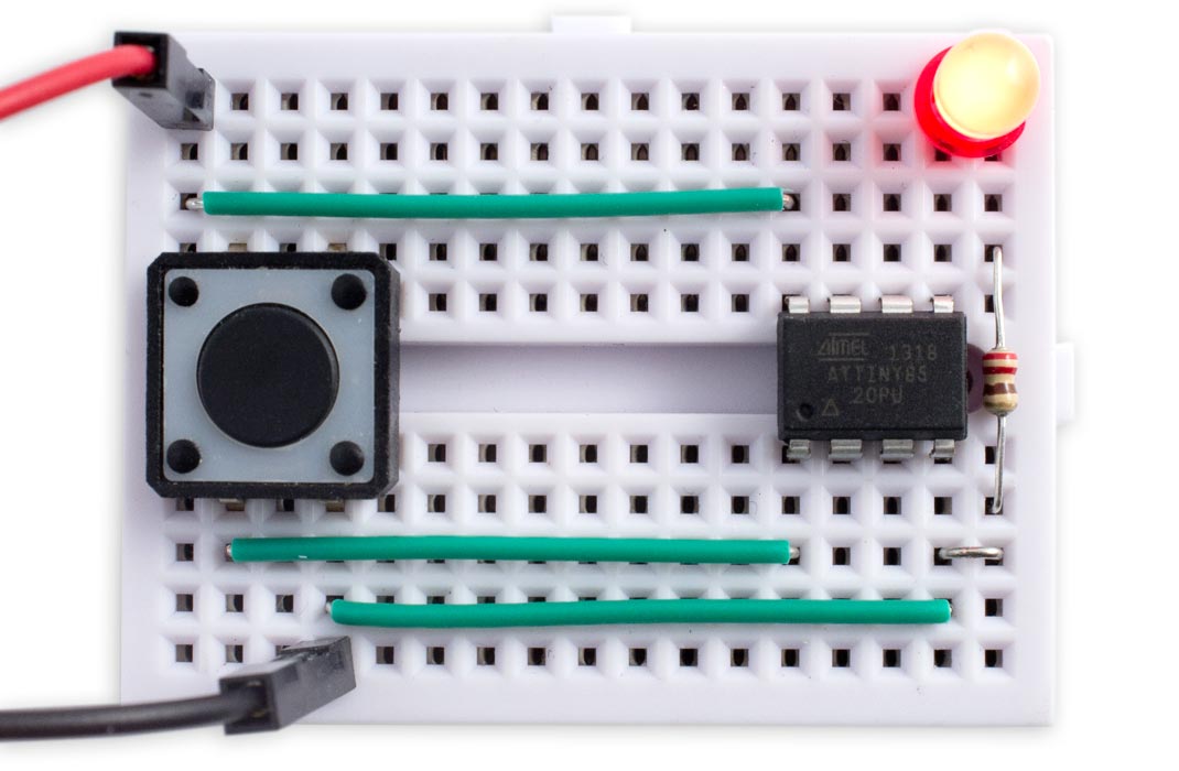
Here's the circuit. It doesn't even need an I/O pin, because it uses the reset line to toggle the processor between running and sleep:
Push-button on/off switch using reset to toggle an ATtiny processor between on and sleep.
In sleep mode the processor uses just 0.5µA, which is negligible.
The on/off state is stored in the variable Power. Usually all variables are initialised on reset, but we want this variable to retain its value; the trick is to declare it with the declaration:
int Power __attribute__ ((section (".noinit")));
Here's the whole program:
#include <avr/sleep.h>

int led = 0;
boolean On = 1;
int Power __attribute__ ((section (".noinit")));

void PowerDown () {
  set_sleep_mode(SLEEP_MODE_PWR_DOWN);
  ADCSRA &= ~(1<<ADEN);       // Turn off ADC to save power
  sleep_enable();
  sleep_cpu();
}

void setup() {
  Power = !Power;
  if (!Power) PowerDown();
  pinMode(led, OUTPUT);
}

void loop() {
  digitalWrite(led, On = !On);  // Toggle the LED
  delay(1000);                  // Wait for a second
}
To kill the power under program control, such as after a period of inactivity, simply call PowerDown().
If you want to switch the power to other components in the circuit you could drive them from an I/O pin. If the other components draw less than 20mA you can drive them direct; otherwise use a P-channel power MOSFET, such as the FQP27P06 (for 5V) or the NDP6020P (for 5V or 3.3V).
The same idea could be used to toggle between off and two or more different modes.
Update
11th October 2022: I have corrected the symbols used for the MOSFETs in the circuit diagrams.
- ^ 555 timer IC - Schmitt trigger on Wikipedia.
- ^ Push-button power switch breakout on Adafruit.
- ^ Horowitz, P. and Winfield Hill (2015), The Art of Electronics - Third Edition, Cambridge University Press, ISBN 978-0-521-80926-9, p. 196, reproduced with permission. Web site: http://artofelectronics.net/.
blog comments powered by Disqus