Minimal RP2040 Board
12th April 2022
This article describes the design and construction of a minimal breakout board based on the Raspberry Pi RP2040 processor:
The Minimal RP2040 Board.
It's designed to fit on a prototyping board as the basis for a complete RP2040 microcontroller.
Introduction
I'd been thinking about designing a project based on the Raspberry Pi RP2040, and to get more familiar with it I decided to try building a minimal RP2040-based computer on a prototyping board.
The RP2040 is a dual-core Arm Cortex-M0+ running at up to 133MHz, with 264 Kbytes of on-chip RAM, and support for up to 16 Mbytes of off-chip flash memory via a QSPI bus. It was designed in Cambridge, UK, by the team behind the Raspberry Pi boards, and is fabricated by TSMC using their 40nm process [1].
The RP2040 seems to have a lot going for it: it has a good set of features, the documentation is excellent [2], there are many useful example programs [3], bare chips are under £1/$1, and unlike many processors at the moment they actually seem to be available [4].
My initial idea was to mount the RP2040 on a breakout board, bringing all the contacts to two rows of 28-way headers, and then mount all the other components on the prototyping board as I did with my earlier projects such as Minimal ATSAMD21 Computer and Minimal ATmega4809 on a Breadboard. However the only QFN56 breakout boards I could find arrange the pins in a square, making them unsuitable for a prototyping board.
I therefore started designing my own breakout board in Eagle. I soon realised that I could reduce the number of header pins by interconnecting the supply lines, and including the decoupling capacitors on the board. The hardware design datasheet [5] gives good advice about laying out a board. It includes a clear explanation of what decoupling capacitors are for; read this if you've ever thought "I don't think I'll bother with those". It also recommends that the paths to the flash chip and crystal should be as short as possible, so I decided to include these on the breakout board too.
The board grew from a simple breakout board to something similar to the Raspberry Pi Pico, so you might wonder why I bothered to design it rather than just buy a Pico. The answer is that I wanted the experience of building my own board, and I wanted a board on which I could easily try out different components, such as different flash chips.
The circuit
Here's the circuit of the RP2040 Board:
Circuit of the Minimal RP2040 Board.
The circuit generally follows the design of the Minimal Design Example in the hardware design datasheet [6]. However I've drawn my version of the circuit slightly differently, with each decoupling capacitor next to the pin it is decoupling to make it clearer.
Unlike many other processors the RP2040 doesn't include flash on chip, but includes a QSPI flash interface to make it easy to interface an external flash chip. I used the recommended part, the Winbond W25Q128JVS, which provides 16Mbytes, the largest amount of flash that the RP2040 will support. You can use any compatible flash chip up to 16Mbytes; see the hardware design datasheet for information about choosing a different flash chip.
Most of the passive components are 0402 size. This is smaller than I usually use so I was a bit apprehensive about working with them, but it wasn't too difficult. I was also amazed at how cheap these components are; I got a pack of 50 100nF capacitors for 15 pence [7]!
For the other components I avoided the smallest package sizes, and chose the versions that are most widely available. The flash memory chip is SOIC, the 3.3V regulator is SOT23-5, and the crystal is 5x3.2mm.
There's a good discussion in the RP2040 hardware design datasheet of how to calculate the crystal capacitors from the crystal's load capacitance. The crystal I chose specifies a load capacitance of 12pF, and using their calculation the crystal capacitors should be 14pF; the values I used, 12pF, are close enough to this (it's a coincidence that this is the same as the load capacitance).
None of the component values are particularly critical, and most of them could be ±10%, apart from the crystal capacitors which should probably be ±5%. The parts in the following parts list are just suggestions.
► Parts list
Construction
I designed a PCB in Eagle and sent it to PCBWay for production:
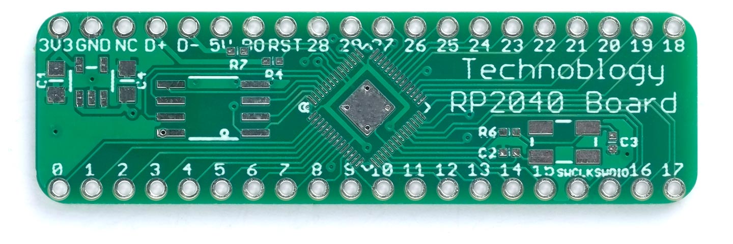
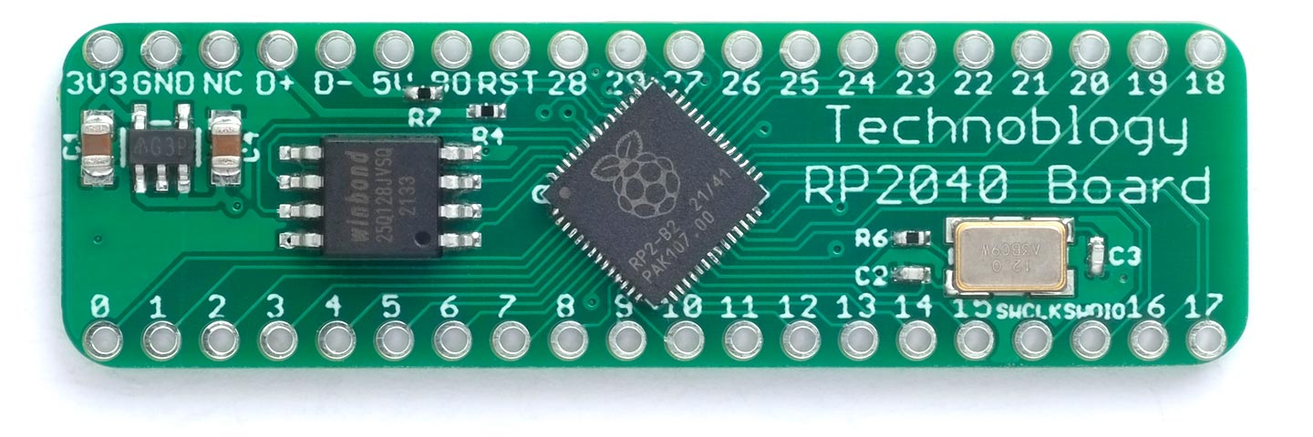
The Minimal RP2040 Board PCB.
My aim was to make the board as small as possible, and it ended up slightly smaller than the Raspberry Pi Pico board.
Unlike on the Raspberry Pi Pico, the pin legends are on the top of the board. The numbers correspond to the pin number in the I/O port, which is the same as the Arduino pin number. They are all in sequence, apart from 28 and 29 which are swapped as that's the only way I could manage the PCB layout. The USB connections are in the same order as on a USB breakout board, so you can plug one onto a prototyping board alongside the appropriate pins.
All the main components are on the top of the board, apart from the decoupling components which are on the bottom of the board to make the PCB layout simpler. The tracks and spacings are 7mil, so you should be able to get it fabricated with the cheapest PCB option.
The RP2040 is only available in one package size, QFN56, and I think it's safe to say that this makes the board impossible to solder with a conventional soldering iron. You'll either need a hot air gun, or a reflow oven. I used a Youyue 858D+ hot air gun set to 275°C. You'll also need a magnifying glass for examining the board.
My procedure for assembling the board is described in the following sections.
RP2040
The hardest component to solder is the RP2040, so I started with this.
I used a pin to spread a thin line of solder paste [8] on the PCB along each of the four sides of the QFN56 pad. I examined it with a hand lens to check that every pin had some solder paste, and that there wasn't too much in one place, if necessary adjusting it with the pin.
I also put a small blob of solder paste in the centre of the pad; this is essential as it's the ground connection.
I then used a pair of tweezers [9] to pick up the RP2040 chip and gently drop it in position. I checked it with the hand lens and gave it a few taps with the tweezers to centre it up perfectly.
I then heated up the chip with the hot air gun until I could see the solder glistening along all four edges of the package.
Inevitably there may be some solder bridges between some of the package pins, and I used a conventional soldering iron with a fine tip to remove these. I avoid using solder braid as I find that this scratches the PCB; instead I stripped a short section of insulation from a fine stranded cable, dipped it in flux, and then used this to soak up the excess solder on each solder bridge.
Decoupling capacitors
The next step was to solder the 0402 components on the bottom of the PCB:
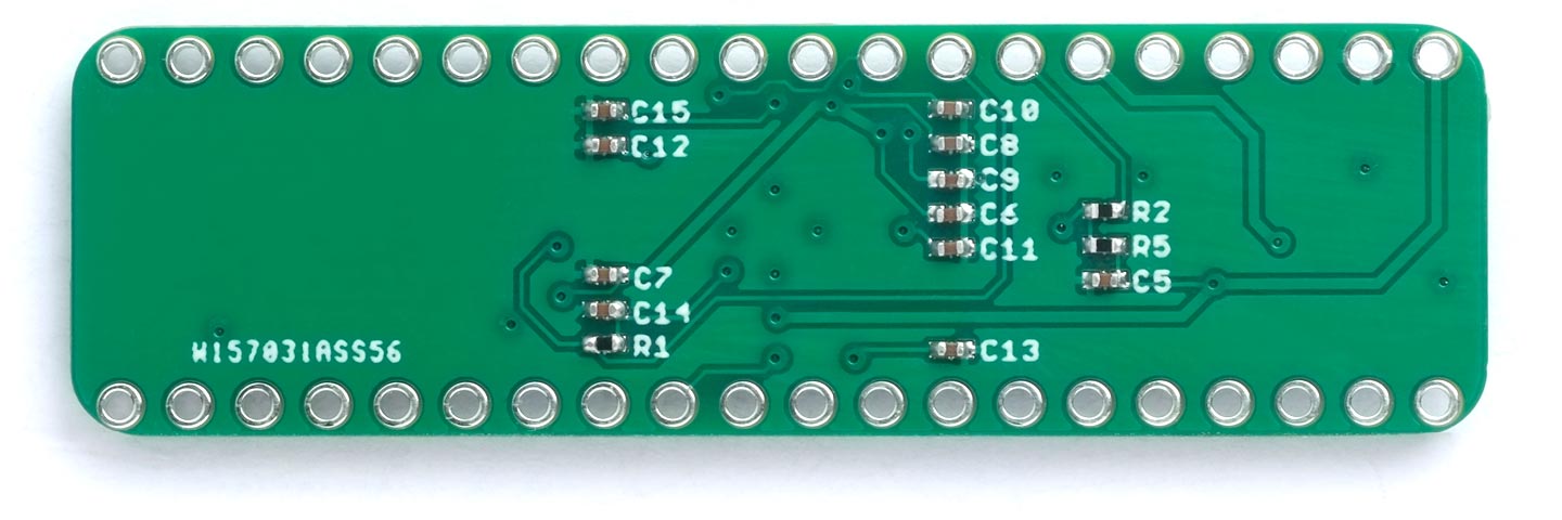
The bottom of the Minimal RP2040 Board, showing the decoupling capacitors and other components.
As this was the first time I'd worked with 0402 components I found it a bit of a challenge. When picking them up with the tweezers it's easy to accidentally flick them across the room, and they also tend to blow away if you get the hot air gun too close! I recommend ordering a few spares in case this happens.
Other components
Finally I soldered the remaining components on the top of the board, again using the hot air gun.
Connecting up
Before connecting up the board I recommend doing the following checks:
- With a continuity tester check between adjacent RP2040 pins to ensure that you haven't missed any solder bridges. I used my Continuity Tester. Most of the pins come to header pins, making this relatively easy.
- Apply power to the 5V input, initially starting it at 3.3V, and monitor the current consumption, which should be around 10mA.
- Check the DVDD voltage, on pin 45 of the RP2040, which should be 1.1V.
- Then increase the voltage to 5V and check that the regulated output on the 3.3V header pin is correct.
If this all seems OK you could go ahead and try uploading and running a sample program.
Running programs
The next step is to fit headers to the Minimal RP2040 Board, fit it on a prototyping board with a USB connection and an LED, and try running the Blink example program.
Connecting USB
One option is to make a USB cable using a length of four-core ribbon cable and a USB DIY Connector Shell [10], with a five-pin header at the other end to plug into the prototyping board. Alternatively, you can plug a USB breakout board directly into the prototyping board, as the pins are designed to line up. They are available from Adafruit [11] or AliExpress. Also connect an LED in series with a 220Ω resistor between GND and pin 25, which the core defines as LED_BUILTIN:
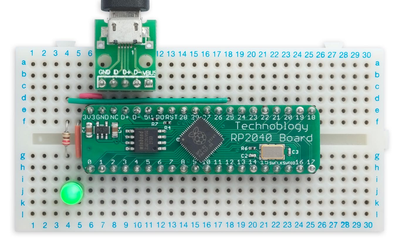
Uploading Blink to the Minimal RP2040 Board.
Installing the RP2040 core
I recommend Earle Philhower’s Raspberry Pi RP2040 Boards core which supports a wide range of RP2040 boards, supports more Serial, SPI, and I2C ports, and gives significantly better performance than the Arduino RP2040 core. For instructions on how to install it see: https://github.com/earlephilhower/arduino-pico.
Running Blink
To check that the board is working try running some example programs, such as Blink.
- Select Raspberry Pi RP2040 Boards from the Board menu, and Generic RP2040 from the submenu.
There are three entries for each board; for example:
Generic RP2040
Generic RP2040 (Picoprobe)
Generic RP2040 (pico-debug)
Select the first of these three options (the others are for debugging).
- Set Flash Size to the appropriate option for the SPI Flash chip you've used. If like me you used a 128Mbit chip choose the 16MB option, and choose the one with FS to allocate space for use by LittleFS.
- Set Boot Stage 2 to W25Q080 QSPI /2, which is appropriate for the fastest Winbond W25Q series flash chips.
You can leave all the other options at their defaults.
- Upload Blink to the board from the Examples, 01.Basics submenu.
You should then see the LED giving one-second flashes.
Putting the board into upload mode
If the upload fails you may need to put the board into upload mode first.
- Connect the Boot pin, marked BO on the edge connector, to GND.
- Connect the RST pin briefly to GND.
- Disconnect the Boot pin.
You could connect push buttons between GND and the RST and BO pins to make this easier.
Running uLisp
You can also try running uLisp, my Lisp for microcontrollers:
- First download the latest ARM version of uLisp from the Download uLisp page.
- Upload uLisp to the board.
You should then be able to select the USB port from the Port menu, select Serial Monitor from the Tools menu, and enter Lisp commands.
For more information about the version of uLisp for the RP2040 see uLisp - RP2040 boards.
Resources
Get the Eagle files for the PCB here: https://github.com/technoblogy/minimal-rp2040-board.
Or order boards from OSH Park here: Minimal RP2040 Board.
Or order boards from PCBWay here: Minimal RP2040 Board.
Update
14th April 2022: Added the 1.1V supply to the circuit diagram.
10th August 2022: I've corrected the value of R5 on the circuit diagram; thanks to JeonLab for pointing this out.
- ^ Raspberry Pi: Here's how we built our own chip to power the Pico on ZDNet.
- ^ RP2040 Datasheet on raspberrypi.com.
- ^ Pico examples on GitHub.
- ^ Raspberry Pi RP2040 Microcontroller on The Pi hut.
- ^ Hardware Design with RP2040 on raspberrypi.com.
- ^ Hardware Design with RP2040 on raspberrypi.com.
- ^ Yageo 0402 100nF Capacitor on RS Components.
- ^ CHIPQUIK SMD291AX10 Solder Paste on rs-online.
- ^ Precision Straight Tweezers - Rhino SW-11 on Adafruit.
- ^ USB DIY Connector Shell on Adafruit.
- ^ USB Micro-B Breakout Board on Adafruit.
blog comments powered by Disqus