ATtiny10 Thermometer PCB
2nd February 2019
This is a small battery-powered thermometer that displays the temperature as a binary sequence of red and green flashes on a bi-colour LED:
ATtiny10-based thermometer, flashes the temperature on a bi-colour LED.
It consists of an ATtiny10, a DS18B20 1-wire temperature sensor, and a bi-colour LED, and fits on a printed circuit board 19mm (0.75") in diameter including a 12mm CR1225 button cell. To avoid the need for a digital display, and minimise current consumption, the thermometer pulses the temperature as a series of red or green flashes on the bi-colour LED.
It's based on my earlier project ATtiny10 Thermometer, which also gives details of the way in which temperatures are encoded. I designed it so I could seal it in a small waterproof enclosure and put it outside the window, allowing me to see the outdoor temperature from inside. Alternatively it would make an interesting pendant.
The circuit
Here's the circuit of the ATtiny10 Thermometer:
Circuit of the ATtiny10 Thermometer.
Construction
I designed a PCB in Eagle, and ordered a set of boards from PCBWay. Here's the preview from OSH Park:
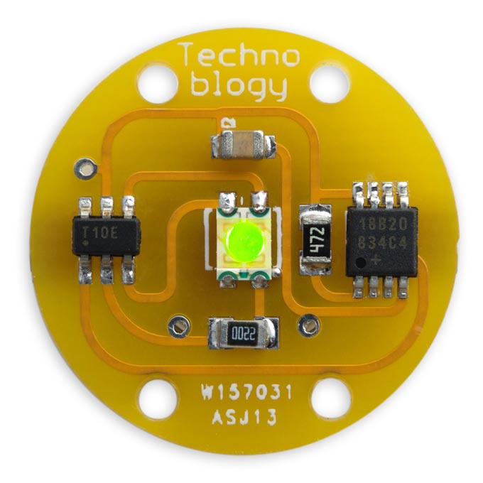
The front and back of the ATtiny10 Thermometer circuit board.
Note that you need to program the ATtiny10 before soldering it on the PCB, because the connection to the DS12B20 interferes with the in-system programming. I temporarily soldered the ATtiny10 to a breakout board to program it, and then transferred it to the PCB when it was successfully programmed.
The ATtiny10 is in an SOT-23 package, and the DS12B20 is in an 8-pin µSOP package [1]. I used 0805 resistors and capacitors. I tried a couple of SMD red/green bi-colour LEDs and chose the Kingbright KPBD-3224SURKCGKC as it was the brightest [2].
I soldered all the SMD components apart from the battery clip using a Youyue 858D+ hot air gun set to 250°C.
The PCB is designed to work with a 3V 12mm coin cell; types 1216, 1220, or 1225 are suitable. The battery fits in an SMD 12mm coin cell holder [3]. I soldered this onto the back of the board with a conventional soldering iron:
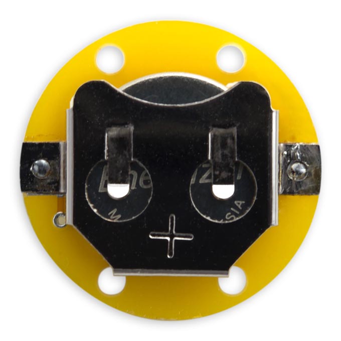
Back of the board showing the battery holder.
The program
The program is the same as my earlier article; see ATtiny10 Thermometer.
Compiling the program
Note that you need to program the ATtiny10 before soldering it on the PCB; see Construction above.
I compiled the program using the ATtiny10Core hardware configuration which you can download from my ATtiny10Core repository on GitHub. Select the ATtiny10/9/5/4 option under the ATtiny10Core heading on the Boards menu. Then choose ATtiny10 from the Chip menu.
I uploaded the program to the ATtiny10 using the USBasp programmer. For more details about the procedure see my earlier article Programming the ATtiny10 [Updated].
Here's the ATtiny10 Thermometer program: ATtiny10 Thermometer Program.
Alternatively, get it on GitHub here together with the Eagle files for the PCB: ATtiny10 Thermometer on GitHub.
Or order a board from OSH Park here: ATtiny10 Thermometer Board.
Updates
27th July 2019: Corrected a mistake in the circuit diagram.
- ^ Maxim DS18B20U+ Temperature Sensor on RS-Online.
- ^ Kingbright KPBD-3224SURKCGKC on Farnell.
- ^ Coin Cell Battery Holder - 10mm (SMD) on Farnell.
blog comments powered by Disqus