Using the ATmega1284 with the Arduino IDE
16th July 2016
The ATmega1284 is a desirable chip to work with: it provides a generous 128 Kbytes of flash memory, 4 Kbytes of EEPROM, and 16 Kbytes RAM, twice as much RAM as the ATmega2560. It also has the advantage that it's available in a DIP package, so it fits on a prototyping board and is easy to wire up, and is nearly half the price of the ATmega2560. Surprisingly there isn't currently an official Arduino board based on it.
Its large RAM capacity makes it the best AVR processor for running programming language interpreters. I wanted to test it as a platform for my uLisp Lisp interpreter for the Arduino, and this article describes my experiences.
Here I describe three alternative ways of programming it with the Arduino IDE:
Using an empty core
If you're not interested in using the Arduino core functions, like millis() and digitalWrite(), the simplest way to program the ATmega1284 from the Arduino IDE is using In-System Programming (ISP) with an empty core, as described in my earlier article Using the Arduino IDE Without Cores.
- Add the following sections to the boards.txt file in the Arduino AVR directory:
##############################################################
atmega1284e8.name=ATmega1284 @ 8 MHz (internal oscillator; BOD disabled)
atmega1284e8.upload.tool=arduinoisp

atmega1284e8.upload.maximum_size=131072
atmega1284e8.upload.maximum_data_size=16384

atmega1284e8.bootloader.tool=avrdude
atmega1284e8.bootloader.low_fuses=0xE2
atmega1284e8.bootloader.high_fuses=0x99
atmega1284e8.bootloader.extended_fuses=0xFF
atmega1284e8.bootloader.unlock_bits=0x3F
atmega1284e8.bootloader.lock_bits=0x3F
atmega1284e8.bootloader.file=empty.hex

atmega1284e8.build.mcu=atmega1284p
atmega1284e8.build.f_cpu=8000000L
atmega1284e8.build.board=AVR_ATMEGA1284E8
atmega1284e8.build.core=empty
atmega1284e8.build.variant=standard
##############################################################
atmega1284e1.name=ATmega1284 @ 1 MHz (internal oscillator; BOD disabled)
atmega1284e1.upload.tool=arduinoisp

atmega1284e1.upload.maximum_size=131072
atmega1284e1.upload.maximum_data_size=16384

atmega1284e1.bootloader.tool=avrdude
atmega1284e1.bootloader.low_fuses=0x62
atmega1284e1.bootloader.high_fuses=0x99
atmega1284e1.bootloader.extended_fuses=0xFF
atmega1284e1.bootloader.unlock_bits=0x3F
atmega1284e1.bootloader.lock_bits=0x3F
atmega1284e1.bootloader.file=empty.hex

atmega1284e1.build.mcu=atmega1284p
atmega1284e1.build.f_cpu=1000000L
atmega1284e1.build.board=AVR_ATMEGA1284E1
atmega1284e1.build.core=empty
atmega1284e1.build.variant=standard
##############################################################
This will add two new options to the Boards menu, for an ATmega1284 with the default 1 MHz internal oscillator, or with an 8 MHz internal oscillator.
Blink program
Here's a Blink program for use with the empty core, using an LED connected via a 220Ω resistor to digital I/O pin PD5 (pin 19):
/* ATmega1284 Blink sketch for use with the empty core */

#include <avr/io.h>
#include <stdint.h>

int led = PORTD5; // In port B

void setup() {
 DDRD = DDRD | 1<<led;         // Define PD5 as an output
}

volatile long Counter;

void delay (long n) {          // Delay by n milliseconds
 Counter = 29 * n;
  do Counter--; while (Counter != 0);
}

// The loop routine runs over and over again forever:
void loop() {
  PORTD = PORTD | 1<<led;      // Take PD5 high
  delay(1000);                 // Wait for a second
  PORTD = PORTD & ~(1<<led);   // Take PD5 low
  delay(1000);                 // Wait for a second
}

// We need main()
int main() {
  setup();
  for(;;) loop();
}
Select the ATmega1284 @ 1 MHz (internal oscillator; BOD disabled) option on the Boards menu which is the default fuse setting on new ATmega1284s. Then upload the program using the Tiny AVR Programmer Board (see ATtiny-Based Beginner's Kit):
Connecting the Tiny AVR Programmer Board to an ATmega1284 for ISP programming.
Alternatively you can use another suitable ISP programmer, such as an Arduino Uno as described in Installing a bootloader below.
Using the 8 MHz internal clock
If you want to reprogram the fuses to use the 8 MHz internal clock download the following file empty.zip, unzip it into empty.hex, and put this in the bootloaders directory, which is in the avr directory containing the boards.txt file. This empty file is needed to allow you to use the Burn Bootloader command to set the fuses, even if you don't actually want to upload a bootloader.
To select the 8 MHz internal oscillator select the ATmega1284 @ 8 MHz (internal oscillator; BOD disabled) option, and choose Burn Bootloader to set the fuses. Then upload the program again and the Blink program should flash eight times faster.
Using an ATmega1284 core
If you want to program the ATmega1284P using ISP, and use the Arduino core functions, the best option is to install Jack Christensen's Mighty 1284P core, which he has updated to work with version 1.6.x of the Arduino IDE [1].
Install the mighty-1284p folder in the hardware folder in your Arduino folder and restart the Arduino IDE. This should add a Mighty-1284p Boards section at the bottom of your Boards submenu with several alternative board definitions.
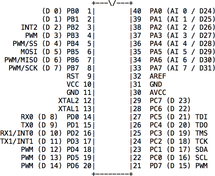
I recommend using the "maniacbug" Mighty 1284p 16MHz using Optiboot option on the Boards menu, which gives the following assignments between the ATmega1284 pins and the Arduino inputs:
Then upload the program using the Tiny AVR Programmer Board as in the previous section (see ATtiny-Based Beginner's Kit). Alternatively you can use another suitable ISP programmer, such as an Arduino Uno as described in Installing a bootloader below.
The standard Arduino Blink program should blink an LED connected to pin 19 of the ATmega1284.
Using a bootloader
If you want to program the ATmega1284P via the serial port, and use the Serial Monitor for debugging, you will need a bootloader. You can either buy an ATmega1284P chip with a bootloader already installed, or install a bootloader yourself using ISP as described in the next section.
To use the ATmega1284P with the Arduino core functions I used Jack Christensen's Mighty 1284P core, which works happily with version 1.6.x of the Arduino IDE [2].
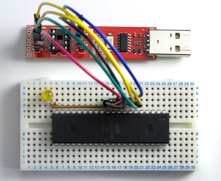
You will also need an FTDI USB-to-serial converter. There are several alternatives available; I used the FTDI Basic Breakout from Sparkfun [3], available from HobbyTronics in the UK [4]:
Connecting an FTDI USB-to-serial converter board to an ATmega1284 for serial programming.
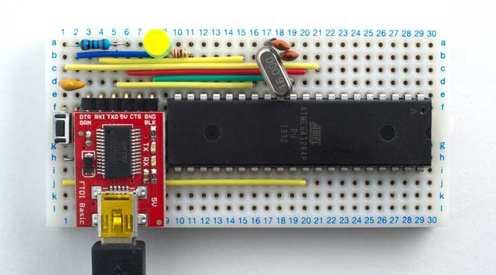
Here's the circuit:
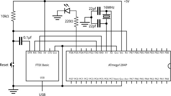
Circuit to connect an FTDI USB-to-serial converter board to an ATmega1284.
You should now be able to upload the standard Arduino Blink program, which should blink an LED connected to pin 19 of the ATmega1284.
Installing a bootloader
Unless you bought an ATmega1284P chip with a bootloader already installed, you'll first need to upload a bootloader using In-System Programming (ISP). Unfortunately the ISP programmer I usually use, Sparkfun's Tiny AVR Programmer, is not compatible with the 128 Kbyte program memory in the ATmega1284. Fortunately you can use an Arduino Uno as an ISP programmer [5]:
Connect the Arduino Uno to the ATmega1284P on the breadboard as follows:
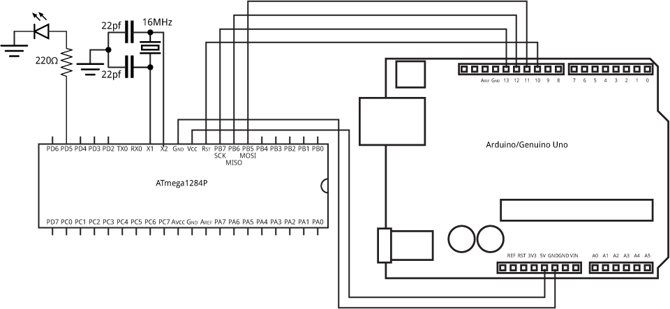
Connecting an Arduino Uno to an ATmega1284 for ISP programming.
Now proceed as follows:
- Install the Mighty 1284P core.
- On the Tools -> Board submenu choose Arduino/Genuino Uno.
- Select the sketch File -> Examples -> 11.ArduinoISP -> ArduinoISP and upload it to the Arduino Uno.
- On the Tools -> Board submenu choose "maniacbug" Mighty 1284p 16MHz using Optiboot.
- Select Tools -> Programmer -> Arduino as ISP.
- Select Tools -> Burn Bootloader.
You should then be able to disconnect the Arduino Uno, connect the FTDI USB-to-serial converter, and upload programs via the USB port.
Update
3rd October 2016: Added the Reset connection, which I'd missed from the circuit diagram of programming an ATmega1284 using an Arduino.
- ^ Mighty 1284P core on Github.
- ^ Mighty 1284P core on Github.
- ^ FTDI Basic Breakout on Sparkfun.
- ^ FTDI Basic Breakout on HobbyTronics.
- ^ Using an Arduino as an AVR ISP on Arduino.cc.
blog comments powered by Disqus