ATtiny-Based Beginner's Kit
28th June 2014
One of the most popular starting points for building microcontroller-based projects is the Arduino Uno, the board based on the popular Atmel ATmega328 and supported by the free Arduino development environment.
However, I'd like to suggest an alternative beginner's kit that costs less, and is in many ways more fun and more educational. My alternative is based on the ATtiny85, which with just 8 pins is one of the smallest microcontrollers in Atmel's AVR range:
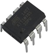
Despite its diminuitive size it's packed with capabilities, and apart from having fewer I/O pins it can do most of what the ATmega328 in the Arduino Uno can do. And you can program it from the same Arduino IDE used with the Arduino Uno.
Here is my recommended kit of parts:
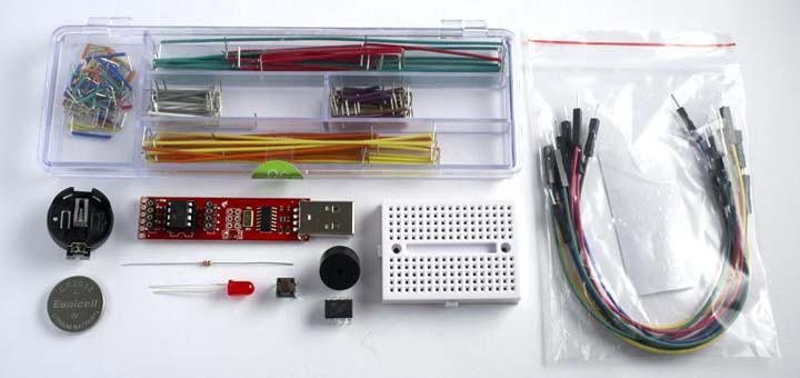
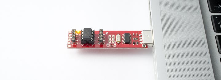
The heart of this kit is the Tiny AVR Programmer from SparkFun, a programmer board that fits directly into a computer's USB port, and allows you to program an ATtiny85 in the on-board socket, or in an external circuit using jumper leads. It can also be used to program other AVR chips, such as the ATtiny84 and ATmega328. It's available from SparkFun [1], or from Proto-PIC in the UK [2].
In addition to this I'd recommend:
- A set of jumper probes to connect between the Tiny AVR Programmer and your own circuits [3].
- A mini breadboard, to build circuits without the need for soldering. I use the ones shown above from SparkFun [4] or HobbyTronics in the UK [5].
- A set of precut jumper wires. I particularly recommend the Pololu ones [6] as they are coded with the resistor colour code so you immediately know which wire to pick. They're available from HobbyTronics in the UK [7].
- A spare ATtiny85 (one is already included with the Tiny AVR Programmer).
- A few additional components for making projects: an LED, a push button, a piezo buzzer, a 220Ω resistor to use with the LED, A CR2032 3V lithium battery, and a breadboard-compatible battery holder (available from SparkFun [8] or Proto-PIC in the UK [9]).
The total cost of all these components is about £25 or $40.
Getting started – set up the Arduino IDE to work with the ATtiny85
If you haven't already got the Arduino IDE installed on your computer, download and install it as described on the Arduino site:
By default the Arduino IDE now supports all the boards released by Arduino, but not the ATtiny processors, so next you need to add support for the ATtiny85.
Although there are one or two alternative cores for the ATtiny processors, by far and away the best of these is Spence Konde's ATTinyCore. This not only supports the ATtiny85 in all of its configurations, but also most of the other ATtiny processors you might want to use in your projects.
For instructions on how to install Spence Konde's ATTinyCore via the Arduino Boards Manager (recommended) see:
ATTinyCore - Boards Manager Installation
Once you have done this you should see a new ATTinyCore section on the Board option on the Tools menu, containing an entry for each ATtiny family.
For more information about using the SparkFun Tiny AVR programmer see their tutorial, although this refers to using David A. Mellis's older ATtiny core which I no longer recommend: [10].
Step one - program the on-board ATtiny85
The first step is to upload a program to the ATtiny85 on the Tiny AVR Programmer board.
Choose the ATtiny25/45/85 (No bootloader) option under the ATTinyCore heading on the Board menu. Then check that the subsequent options are set as follows (ignore any other options):
Chip: "ATtiny85"
Clock Source (Only set on bootload): "1 MHz (internal)"
Specify that you're using the Tiny AVR Programmer by choosing the following option from the Programmer submenu on the Tools menu:
USBtinyISP (ATTinyCore) SLOW, for new or 1 MHz parts
Put an ATtiny85 in the IC socket on the Tiny AVR Programmer board, making sure it's oriented correctly, and plug the Tiny AVR Programmer board into a USB port on your computer.
Open the Blink example from File -> Examples -> 01.Basics.
Click the Upload button.
If all is well the LED connected to I/O line 0 on the Tiny AVR Programmer board should blink once every two seconds.
Step two - program an ATtiny85 on the breadboard
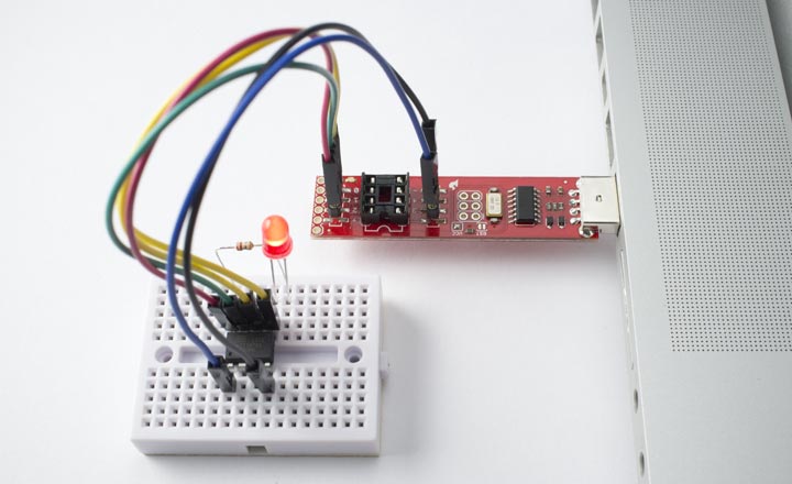
The next step is to build a simple circuit on the breadboard for the Blink project. You only need the ATtiny85, LED, and 220Ω resistor:
Remove the ATtiny85 from the Tiny AVR Programmer.
Connect the 220Ω resistor from VCC (pin 8 on the ATtiny85) to the positive side of the LED (the longer leg), and the negative side of the LED to I/O pin 0 (pin 5 on the ATtiny85)
Now connect the Tiny AVR Programmer to the ATtiny85 on your breadboard, using the jumper leads.
You only need to connect six of the eight connectors:
| Signal | ATtiny85 Pin |
| Reset | 1 |
| GND | 4 |
| MOSI | 5 |
| MISO | 6 |
| SCK | 7 |
| +5V | 8 |
Connect them from the sockets on each side of the IC socket on the Tiny AVR Programmer to the corresponding pin of the ATtiny85 on the breadboard. The circuit on the breadboard will be powered via the 5V from the USB port.
You can then download the program to the ATtiny85 on the breadboard and the LED should flash.
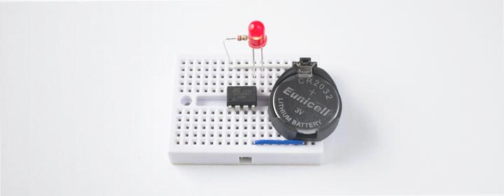
Step three - create a stand-alone circuit
The third step is to disconnect the Tiny AVR Programmer, and add a battery holder and battery. You now have a stand-alone version of your simple Blink application!
If you want to change the program simply remove the battery, plug the jumper leads back in, and upload a new program.
What next?
Here are some suggested projects you could make with these components alone:
- An egg timer - beep the speaker after five minutes (or ten if you like yours hard-boiled).
- A reaction timer - beep the speaker after a random delay, then see how long until the player presses the button. Light the LED if they achieve better than 160ms (the mean for college students).
- A musical doorbell; play a tune through the piezo speaker when the button is pressed.
- A bath level alarm - use wires connected to an analogue input to detect the water level and beep the speaker when the desired level is reached.
- A clock that beeps the time in morse code when you press the button - you'll need to calibrate the ATtiny's internal clock for accurate time.
Update
27th February 2019: I've updated the above steps to describe Spence Konde's ATTinyCore, which is now my recommended core for using the ATtiny85 from the Arduino IDE.
14th August 2022: I've updated the above description to reflect the latest menu options in Spence Konde's ATTinyCore.
- ^ Tiny AVR Programmer on SparkFun.
- ^ Tiny AVR Programmer on Proto-PIC.
- ^ Jumper Wires Premium on Proto-PIC.
- ^ Breadboard - Mini Modular on SparkFun.
- ^ Mini Breadboard from HobbyTronics.
- ^ 140-Piece Wire Kit on Pololu.
- ^ 140 Piece Jumper Wire Kit on HobbyTronics.
- ^ Coin Cell Battery Holder - 20mm on SparkFun.
- ^ Coin cell holder - 20mm on Proto-PIC.
- ^ Tiny AVR Programmer Hookup Guide on SparkFun.
blog comments powered by Disqus