Nano Current Meter
9th October 2019
This project describes a simple low-current meter I devised to check the sleep current of different microcontroller circuits, such as ones based on AVR microcontrollers. It's capable of measuring currents of between 10µA and 30nA with reasonable accuracy, using an ATtiny84 and a few other low-cost parts:
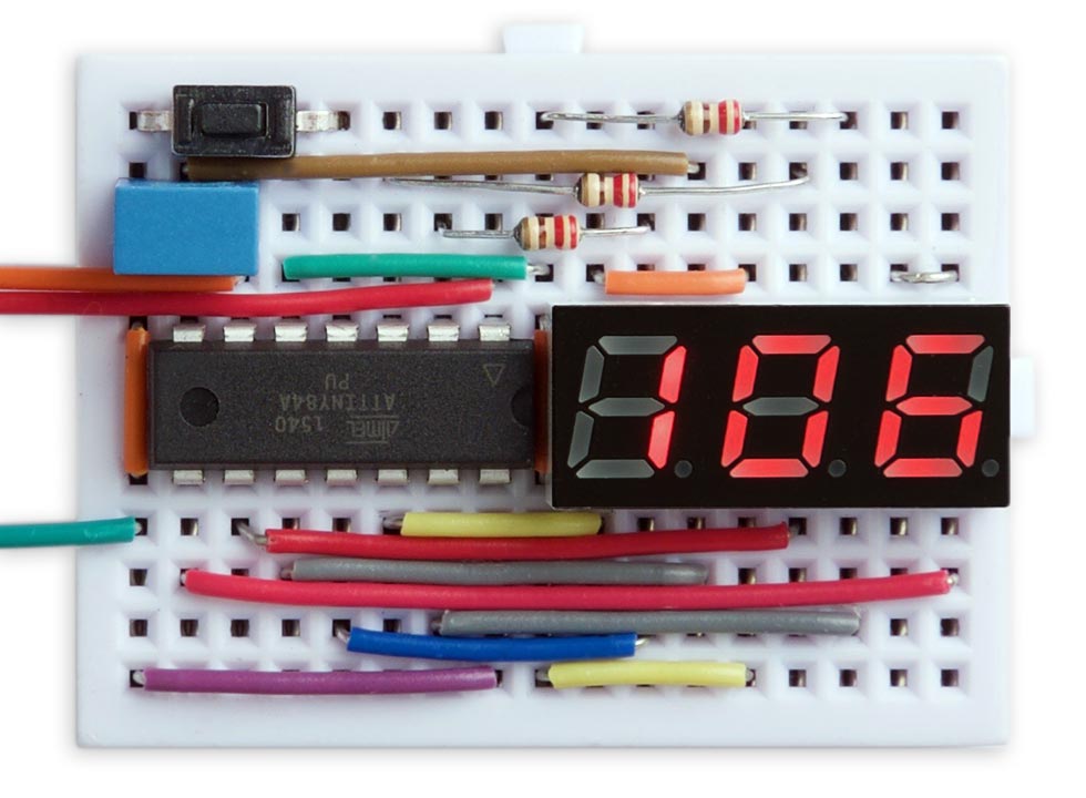
Nano Current Meter based on an ATtiny84, measuring a current of 106nA.
Introduction
Measuring very small currents accurately is notoriously difficult with normal digital multimeters; they either don't provide a low current range at all, or if they do, they create a voltage drop referred to as the "burden voltage" which can render the display inaccurate. One way round this is to use a precision current adapter, such as David L. Jones's µCurrent [1], but such circuits are expensive.
Since I didn't need high accuracy I decided that an alternative approach would be to calculate the current draw based on the time it takes a capacitor to discharge. A capacitor discharging into a resistive load is exponential, like radioactive decay. The voltage halves for successive fixed time intervals, so if the voltage starts at 5V, after a certain time t it will drop to half this value, 2.5V. After a further time t it will drop to 1.25V, and so on. The time t is called the half life.
The half life is log(2) of the time constant RC, or 0.693 x RC. So for a fixed capacitor C, by measuring the time taken for the voltage to drop to 50% of its initial value we can calculate R, the effective resistance of the load, and hence the current consumption.
Using a microcontroller with ADC inputs it's easy to do this, and few other components are needed apart from the capacitor; the downside is that measurements of currents in the nanoamps may take a few seconds while the capacitor discharges.
The circuit
Here's the circuit, roughly reflecting the way it was laid out on the breadboard:
The circuit of the Nano Current Meter, based on an ATtiny84.
The circuit is based on an ATtiny84 and a 0.28" three-digit common anode seven-segment LED display I bought on eBay from a supplier in Shenzhen.
Pins PA0 to PA6 from Port A are used to drive the segments, and PB0 to PB2 on Port B are used to drive the digits. Because there aren't any more pins available PB2 doubles up as a driver for the decimal point, which works because the decimal point is not needed on the third digit. The remaining pin, PA7, is used as an analogue input to measure the voltage across the capacitor.
For the capacitor I chose a DC film capacitor with a tolerance of ±5% [2]. Any good quality capacitor would probably be suitable, but avoid electrolytics as they have a wide tolerance.
A pushbutton connects to the reset input; this is used to initiate a reading.
I powered the circuit from a regulated 5V power supply. If you want to run it from batteries you should include a regulator, as the accuracy of the analogue input depends on the supply voltage.
Using the Nano Current Meter
Connect the test circuit between the Test and Gnd terminals, and press the Reset button. The program first applies 5V to the Test terminal to charge the 1µF capacitor. Then, after short delay it disconnects power, leaving the test circuit to draw power from the capacitor.
When the capacitor has discharged to the target voltage the program calculates the discharge current, and displays it in nA or µA; uA is indicated by a "u" suffix". For example, some possible displays are as follows:
| Sample display | Description |
| Lo | Current < 30nA |
| 45 | Current = 45nA |
| 750 | Current = 750nA |
| 2.5u | Current = 2.5µA |
| 10u | Current = 10µA |
| Hi | Current > 10µA |
Note that the Nano current meter can take up to 100 seconds to measure currents as low as 30nA.
If you're testing the current consumption of a circuit in sleep, power the circuit from the Nano Current Meter's Test terminal, and when the circuit has gone to sleep press the Reset button.
The program
Multiplexing the display
As in several of my previous projects, the display is generated under interrupt, using the contents of the array Buffer[]. For example, to display "123" execute:
Buffer[0]=1; Buffer[1]=2; Buffer[2]=3;
The program uses Timer/Counter1 to generate an interrupt at 200Hz, which is used to multiplex the display. This leaves Timer/Counter0 free for use by millis() etc. Timer/Counter1 is set up by SetupDisplay():
void SetupDisplay () {
  TCCR1A = 0<<WGM10;
  TCCR1B = 1<<WGM12 | 2<<CS10;  // Divide by 8
  OCR1A = 4999;                 // Compare match at 200Hz
  TIMSK1 = 1<<OCIE1A;           // Enable compare match interrupt
}
The interrupt service routine simply calls DisplayNextDigit():
ISR(TIM1_COMPA_vect) {
  DisplayNextDigit();
}
This selects the next digit, sets the appropriate pattern of segments on the digit, and then takes the digit's common anode high:
void DisplayNextDigit () {
  DDRB = 0;                                    // All low
  digit = (digit+1) % ndigits;
  char segs = charArray[Buffer[digit]];
  DDRA = DDRA & 0x80;                          // All inputs
  // Set display segments
  if (dp == digit && dp != 2) DDRB = 1<<DDB2;
  PORTA = (PORTA & 0x80) | (~segs & 0x7F);     // 1 = low
  DDRA = (DDRA & 0x80) | (segs & 0x7F);        // 1 = output
  DDRB = DDRB | 1<<digit;                      // Current digit output
  PORTB = 1<<digit;                            // Current digit high
}
The top bit of PORTA is masked off to avoid interfering with the Test signal.
Timing the capacitor discharge
The main program runs when you press the Reset button to initiate a reading. It first takes the output PA7 high, to charge the capacitor. It then redefines it as an input, and calls analogRead() to monitor the decaying voltage on the input.
When the voltage has fallen to the value defined by Target the program calculates the resistance of the load, based on the RC time constant corresponding to the discharge rate, using the equation:
half life = log(2) RC
To minimise the effect of the changing voltage on the circuit being monitored I chose to set the target at half the half life, which is when the voltage has fallen to 1/√2 of its initial value, or about 3.5V. In the program I use 29/41, which is a good approximation to 1/√2. We simply have to double this time to get the actual half life.
The program then converts this to the discharge current at 5V, which is given by:
discharge current = (5 x log(2) x 10-6) / t
where the discharge current is in amps, 5 is the supply voltage in volts, 10-6 is the capacitance of the discharge capacitor, 1µF, and t is the half life in seconds. This gives:
nA = 1732868 / Time;
where nA is the discharge current in nA, and Time is in milliseconds.
Here's the main loop:
void loop() {
  pinMode(7, OUTPUT);
  digitalWrite(7, HIGH);
  delay(500);
  pinMode(7, INPUT);
  unsigned long Start = millis(), Time, nA;
  unsigned int Initial = analogRead(7);
  unsigned int Target = (Initial * 29) / 41;
  do {
    Time = millis() - Start;
  } while (analogRead(7) > Target && Time < 100000);
  nA = 1732868 / Time;
  dp = 2;
  if (Time >= 100000) { Buffer[0] = Lo; Buffer[1] = Lo+1; Buffer[2] = Space; }
  else if (nA < 1000) { dp = 2; Display(nA); }
  else if (nA < 10000) { dp = 0; Display(nA/10); Buffer[2] = uA; }
  else if (nA < 100000) { dp = 2; Display(nA/100); Buffer[2] = uA; }
  else { Buffer[0] = Hi; Buffer[1] = Hi+1; Buffer[2] = Space; }
  pinMode(7, OUTPUT);
  digitalWrite(7, HIGH);
  for (;;);
}
The last few lines of the program cater for the different display formats described above.
Compiling the program
I compiled the program using Spence Konde's ATTiny Core [3]. Choose the ATtiny24/44/84 option under the ATTinyCore heading on the Board menu. Then check that the subsequent options are set as follows (ignore any other options):
Chip: "ATtiny84"
Clock: "8 MHz (internal)"
B.O.D: "B.O.D. Disabled"
Pin Mapping: "Clockwise (like damellis core)"
By default the ATtiny84 runs at 1MHz. Choose Burn Bootloader to set the fuses for 8MHz operation. Then upload the program using ISP (in-system programming) using a programmer such as Sparkfun's Tiny AVR Programmer Board [4].
Here's the whole Nano Current Meter program: Nano Current Meter Program.
- ^ The µCurrent on AlternateZone.com.
- ^ DC Film Capacitor, Metallised, 1 µF, 63 V on Farnell.co.uk.
- ^ ATTinyCore on GitHub.
- ^ Tiny AVR Programmer on SparkFun.
blog comments powered by Disqus