Audio Pitch Shifter
11th February 2017
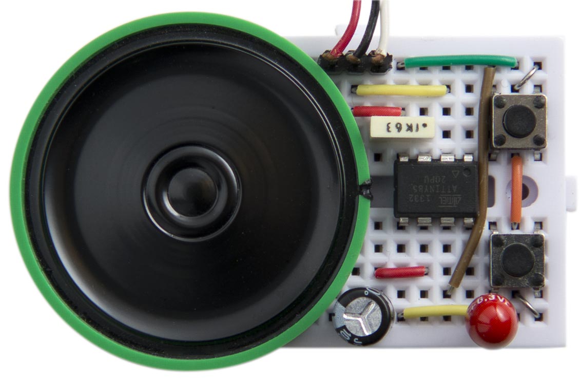
This article describes a simple device based on an ATtiny85 that takes an audio input, shifts its pitch up or down in real time, and plays it through a loudspeaker. You can increase or decrease the pitch shift using two pushbuttons:

Audio Pitch Shifter, based on an ATtiny85, allows you to increase or decrease the pitch of an audio input.
For example, you can plug in an mp3 music player or phone, play some music, and change the pitch of a male singer's voice to a female voice as it's playing.
Although the result is not hi-fi quality, it's an excellent demonstration of how much you can achieve with a single ATtiny85. The chip first amplifies the input by a factor of x20, digitizes it, stores the samples in a circular buffer under interrupt, reads samples back from the circular buffer under a separate timer interrupt, and finally converts the processed digital signal back to analogue, using high-speed PWM, and outputs it to a loudspeaker. Two pushbuttons cause interrupts which change the pitch shift up or down.
The circuit
Here's the full circuit:

The Audio Pitch Shifter circuit, based on an ATtiny85.
How it works
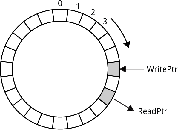
The audio pitch shifter works by continuously sampling the input audio, digitizing it to 8-bit samples, and writing the samples to a buffer. Each sample is written to the buffer using a pointer WritePtr, which is then incremented to the next element in the buffer. When WritePtr reaches the end of the buffer it goes back to the first element, so the buffer is circular:

How the Audio Pitch Shifter buffer works.
In this application the buffer is 256 bytes long, which fits within the memory of the ATtiny85. This makes it easy to implement a circular buffer; we simply truncate WritePtr to a byte after incrementing it. Because we are sampling at approximately 18kHz the buffer represents about 14msec of audio.
The next step is to read samples from the buffer using a second pointer, ReadPtr. If these samples were read at the same rate as the WritePtr samples the two audio streams would be identical. However, by increasing the ReadPtr sample rate we can shift the pitch up, and by decreasing it we can shift the pitch down. For example, reading at a 36kHz sample rate will shift the audio up an octave.
The pitch shift happens in real time, without affecting the tempo of the music, so it's quite different from simply speeding up or slowing down playback of a sample.
Sampling the input
The first part of the audio processing consists of sampling the audio input, using a pair of differential inputs with a gain of x20. The ADC is set up as follows:
  ADMUX = 2<<REFS0 | 1<<ADLAR | 7<<MUX0;  // Internal 1.1V ref, ADC2 vs ADC3, x20
  // Enable, auto trigger, interrupt, 250kHz ADC clock:
  ADCSRA = 1<<ADEN | 1<<ADSC | 1<<ADATE | 1<<ADIE | 5<<ADPS0;
  ADCSRB = 1<<7 | 0<<ADTS0;               // Bipolar, free-running
This sets up the ADC with the following options:
| Option | Description |
| 2<<REFS0 | Internal 1.1V reference. |
| 1<<ADLAR | Left-adjusted data register. |
| 7<<MUX0 | Differential inputs ADC2 (PB4) and ADC3 (PB3) with a gain of x20. |
| 1<<ADEN | ADC enabled. |
| 1<<ADSC | Start conversions. |
| 1<<ADATE | Auto triggering. |
| 1<<ADIE | Enable the ADC conversion interrupt. |
| 5<<ADPS0 | Select a prescaler of divide by 32, giving an ADC clock of 250kHz. |
| 1<<BIN | Bipolar input mode (BIN = 7). |
| 0<<ADTS0 | Free running mode. |
For more information about these settings look at the ATtiny85 datasheet.
Since the ADC conversion takes 14 clock cycles the sample rate will be approximately 250/14 or 17.9kHz. When each conversion is complete an ADC interrupt occurs.
A simplified version of the ADC interrupt service routine is as follows:
ISR (ADC_vect) {
  Buffer[WritePtr] = ADCH + 128;
  WritePtr = (WritePtr + 1) & 0xFF;
}
This reads the ADC value and writes it into the array Buffer[]. Because we're using bipolar input mode the ADC reading is a signed 8-bit value, in the range -128 to 127, so we add 128 to make it an unsigned 8-bit value. The array pointer WritePtr is then incremented, and truncated to 8 bits to make it wrap around, giving a circular buffer of 256 bytes.
Since we are only interested in 8-bit accuracy the ADC is configured with ADLAR=1 to left-adjust the data, so we can read the top 8 bits from the ADCH register and ignore the ADCL register.
Outputting the samples
The next part of the audio processing uses Pulse-Width Modulation (PWM) to convert the 8-bit digital samples to analogue. It takes advantage of the special 64MHz Phase-Locked Loop (PLL) clock option in the ATtiny85 which you can use to drive Timer/Counter1 for fast digital-to-analogue conversion. First we set up Timer/Counter1 for PWM output:
  TIMSK = 0;                              // Timer interrupts OFF
  TCCR1 = 1<<PWM1A | 2<<COM1A0 | 1<<CS10; // PWM OCR1A, clear on match, 1:1 prescale
  OCR1A = 128;
  pinMode(1, OUTPUT);                     // Enable OC1A PWM output pin
The frequency of the PWM square wave is specified by OCR1C; we leave it at its default value, 255, which divides the 64MHz clock by 256, giving 250kHz. The values we want to output are written to OCR1A, which varies the duty cycle. If OCR1A is 0 the PWM waveform is almost always off, giving an analogue output of almost zero. If OCR1A is 255 the PWM waveform is always on, giving an analogue output of VCC.
Timer/Counter0 is used to generate an interrupt to output the samples:
  TCCR0A = 2<<WGM00;                      // CTC mode
  TCCR0B = 2<<CS00;                       // /8 prescaler
  OCR0A = 55;                             // 17.9kHz interrupt
  TIMSK = TIMSK | 1<<OCIE0A;              // Enable interrupt
The rate of this interrupt is the 8MHz system clock divided by a prescaler of 8, and an initial value in OCR0A of 55+1, giving 17.9kHz. This is the same as the ADC sample rate, so initially the audio will play at normal speed.
The interrupt calls an Interrupt Service Routine ISR (TIMER0_COMPA_vect) which reads the next sample from the circular buffer and outputs the sample to OCR1A:
ISR (TIMER0_COMPA_vect) {
  OCR1A = Buffer[ReadPtr];
  ReadPtr = (ReadPtr + 1) & 0xFF;
}
As in the ADC interrupt service routine, the ReadPtr is incremented and truncated to make it wrap around when it reaches the end of the buffer.
Changing the pitch
Two pushbuttons are provided to increase or decrease the pitch shift. These are configured to give a pin-change interrupt when they're pressed:
  pinMode(0, INPUT_PULLUP);
  pinMode(2, INPUT_PULLUP);
  PCMSK = 1<<PINB0 | 1<<PINB2;            // Pin change interrupts on PB0 and PB2
  GIMSK = GIMSK | 1<<PCIE;                // Enable pin change interrupt
The pin-change interrupt service routine simply reads which button was pressed, and then increments or decrements OCR0A to change the output sample rate, and hence the pitch of the audio. Each time you press a button the value of OCR0A increases or decreases by 1.
Smearing the samples
The above version of the ADC interrupt service routine works quite well, but with some pitch shifts there are audible clicks when the two pointers cross. To reduce this effect the final version of the pitch shifter averages the two adjacent samples when writing into the buffer. Here's the revised code:
ISR (ADC_vect) {
  Buffer[LastPtr] = New;
  New = ADCH + 128;
  Buffer[WritePtr] = (Buffer[WritePtr] + New)>>1;
  LastPtr = WritePtr;
  WritePtr = (WritePtr + 1) & 0xFF;
}
It's not much more complicated but gives a noticeable improvement in sound quality.
Other applications
This Audio Pitch Shifter could be used as a voice-changer, or as a special effect in a synthesiser or audio processor.
Driving an audio amplifier
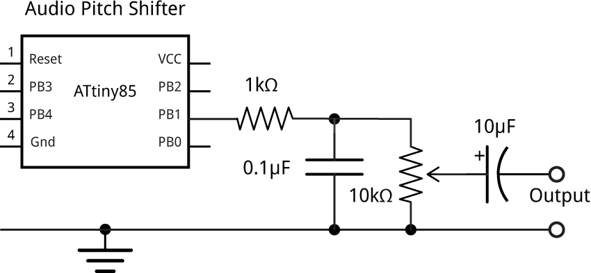
In the above circuit the loudspeaker acts as a low-pass filter, so it's not affected by the 250kHz PWM carrier frequency. If you want to feed the output to an audio amplifier you should include a low-pass filter, consisting of a 1kΩ resistor and a 0.1µF capacitor; otherwise you risk overloading the amplifier:

Connecting the Audio Pitch Shifter to an audio amplifier.
Increasing the sensitivity
For simplicity the above program takes the top 8 bits of the 10-bit digital sample and ignores the bottom 2 bits. You could increase the sensitivity by x4 by instead taking the bottom 8 bits of the digital sample, with account of the sign bit. To do this change the value of ADMUX in setup() to:
ADMUX = 2<<REFS0 | 0<<ADLAR | 7<<MUX0; // Internal 1.1V ref, ADC2 vs ADC3, x20
and replace ISR (ADC_vect) with:
ISR (ADC_vect) {
  uint8_t low = ADCL;
  Buffer[WritePtr] = ((ADCH<<8 + low) - 0x80) & 0xFF;
  WritePtr = (WritePtr + 1) & 0xFF;
}
Compiling the program
Compile the program using Spence Konde's ATTiny Core, which supersedes the various earlier ATtiny cores [1]. Choose the ATtiny25/45/85 (No bootloader) option under the ATTinyCore heading on the Board menu. Check that the subsequent options are set as follows (ignore any other options):
Chip: "ATTiny85"
Clock Source (Only set on bootload): "8 MHz internal"
Choose Burn Bootloader to set the fuses appropriately. Then upload the program using ISP (in-system programming); I used Sparkfun's Tiny AVR Programmer Board; see ATtiny-Based Beginner's Kit.
Here's the whole Audio Pitch Shifter program: Audio Pitch Shifter Program.
Updates
12th February 2017: Made an adjustment to the initial output rate after making measurements with a signal generator.
1st September 2020: Corrected the length of audio in the buffer to 14ms - thanks user zmaj!
24th January 2023: Updated the Compiling the program section to reflect the latest version of ATTinyCore.
- ^ ATTinyCore on GitHub.
blog comments powered by Disqus
