Five LEDs Puzzle
15th December 2020
This project is a logic puzzle for the festive season in which the aim is to get all five LEDs to stay lit up:
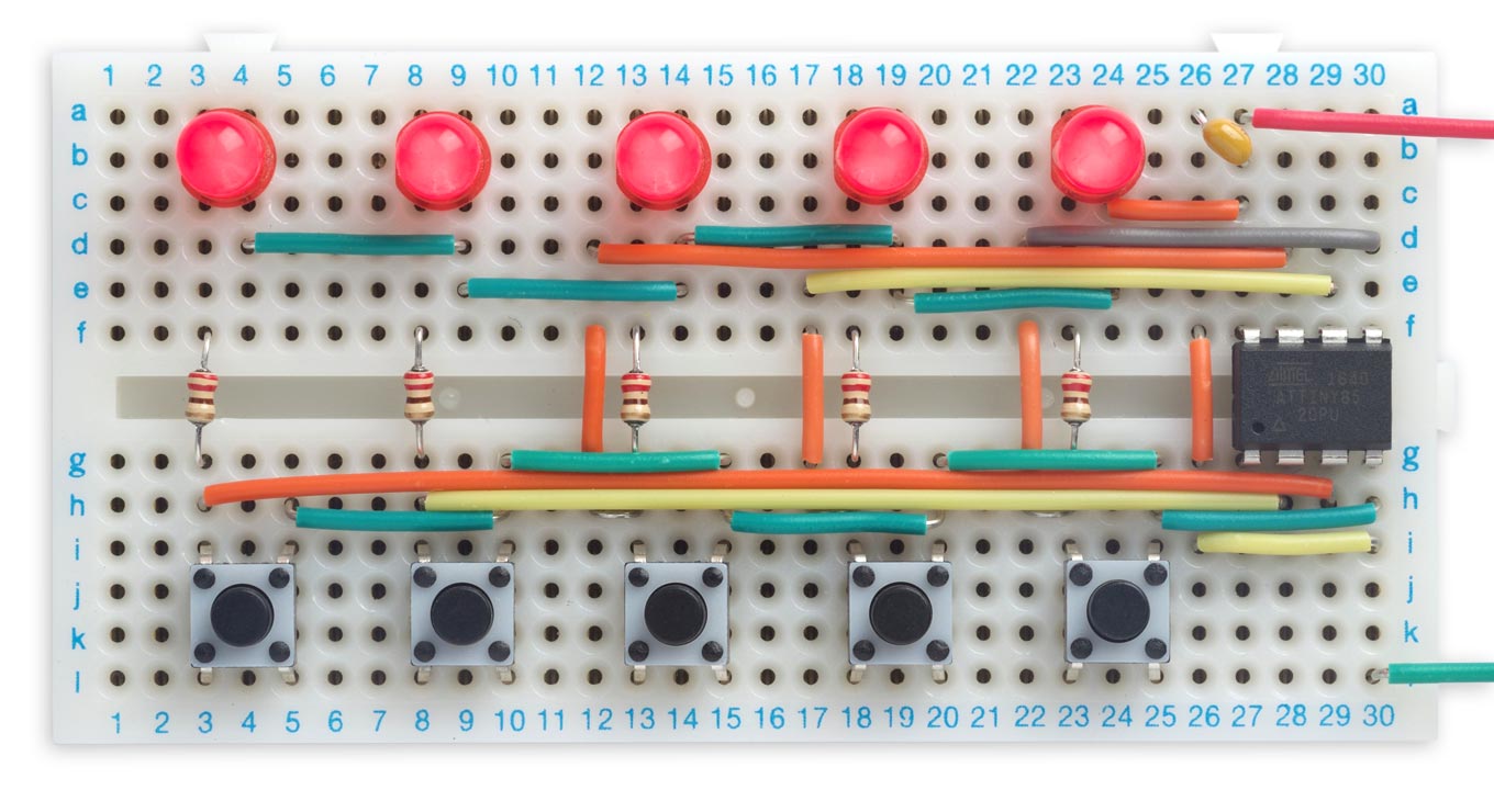
The Five LEDs Puzzle, in which you have to press the buttons to light up all the LEDs.
It consists of five LEDs, five buttons, and an ATtiny85 processor. Each LED lights up briefly when you press the corresponding button below it, but an LED only stays lit under certain conditions; to solve the puzzle you need to work out what the rule is.
Hint: You can solve the puzzle by pressing one button at a time; you don't need to press combinations. To return the puzzle to the starting position, with all LEDs off, disconnect and reconnect power.
For a PCB version of this puzzle see Five LEDs Puzzle PCB.
For the solution see Five LEDs Puzzle Solution.
The circuit
There aren't any clues in the circuit, which is very straightforward:
Circuit of the Five LEDs Puzzle, based on an ATtiny85.
The processor is an ATtiny85 in a PDIP package, but an ATtiny25 or ATtiny45 should also work. For the pushbuttons I used 6mm square through-hole pushbuttons [1], and I built the whole circuit on a 360 hole breadboard [2] as usual using Pololu pre-cut jumper wires, available from HobbyTronics in the UK [3].
The circuit can be run from any suitable 3V to 5V supply, such as a 3.7V Lipo cell, or a pair of AAA batteries in series.
The program
Here's the whole program. I haven't made any effort to make it understandable; after all, that's part of the puzzle!
void setup() {
  PORTB = 0;
  DDRB = 0;
}

void loop() {
  for (int b=0; b<5; b++) {
    int d = DDRB;
    DDRB = d & ~(1<<b);
    PORTB |= 1<<b;
    delay(1);
    if (!(PINB & 1<<b)) {
      while (!(PINB & 1<<b));
      PORTB &= ~(1<<b);
      DDRB = d ^ ((!b || (d & ((1<<b)-1)) == 1<<(b-1))<<b);
    } else {
      PORTB &= ~(1<<b);
      DDRB = d;
    }
    delay(10);
  }
}
I'll explain the program when I give the solution in a later post.
Compiling the program
I compiled the program using Spence Konde's ATTiny Core [4]. Choose the ATtiny25/45/85 option under the ATTinyCore heading on the Board menu. Then check that the subsequent options are set as follows (ignore any other options):
Chip: "ATtiny85"
Clock: "1 MHz (internal)"
This is the default configuration for a new chip, but if you've used other settings choose Burn Bootloader to set the fuses appropriately. Then upload the program using ISP (in-system programming); I used Sparkfun's Tiny AVR Programmer Board; see ATtiny-Based Beginner's Kit.
Happy puzzling!
Update
9th January 2021: Added code to turn on the pullup resistor when reading an input for more reliable operation as the battery voltage decreases, or when using yellow LEDs, as suggested by JChristensen.
- ^ Alcoswitch FSM4JH Tactile Switch on Farnell.
- ^ AD-100 Advanced Solderless Breadboard on Rapid Electronics.
- ^ 140 piece Jumper Wire Kit on HobbyTronics.
- ^ ATTinyCore on GitHub.
blog comments powered by Disqus