Five LEDs Puzzle PCB
4th January 2021
Last month I gave the circuit and program for a puzzle consisting of five LEDs, five pushbuttons, and an ATtiny85. The aim of the puzzle was to find the sequence of button presses that will light up all five LEDs.
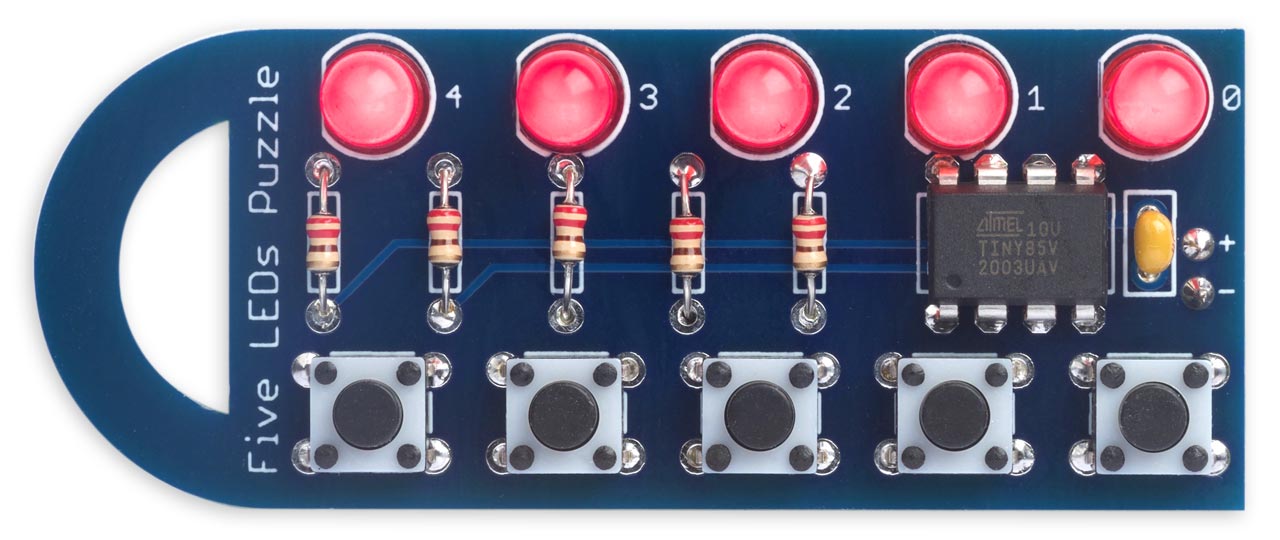
Since building the original Five LEDs Puzzle on a prototyping board I've now designed a PCB version of the puzzle:
I've included details, together with information about getting the PCBs, in case you want to build yourself a board. I also describe an update to the program to make it go to sleep after a delay, to save power and avoid the need for an on/off switch.
The circuit
The PCB version of the Five LEDs Puzzle uses exactly the same circuit as the original prototype:
Circuit of the Five LEDs Puzzle, based on an ATtiny85.
The PCB is designed to use through-hole components to make it easy to solder.
I recommend using red LEDs as they have the lowest forward voltage. For the processor I recommend using an ATtiny85V as it works down to 1.8V, so you may get a slightly longer battery life. Program it using Spence Konde's ATTinyCore [1]. You can program it before you solder it in; alternatively you can temporarily piggy-back an 8-pin DIL socket (the sort with flat legs) on top of the chip once it has been soldered in [2], and plug leads from the programmer into the socket.
The PCB is designed to fit on top of a standard battery pack containing two AAA batteries; I fitted it in place with two double-sided self-adhesive foam pads:

► Parts list
The program
I've updated the program so it automatically goes to sleep if you haven't pressed any button for 30 seconds. This ensures that you don't accidentally leave it switched on, and avoids the need for an on/off switch. The power consumption in sleep is less than 0.05µA, so the drain on the battery is negligible. To wake the puzzle up just press any button.
The following lines are added to setup() to set up pin change interrupts on the five I/O lines, turn off the ADC to save power, and set the power-down sleep mode:
  // Set up pin change interrupts for buttons
  PCMSK = 1<<PINB0 | 1<<PINB1 | 1<<PINB2 | 1<<PINB3 | 1<<PINB4;
  // Disable ADC to save power
  ADCSRA &= ~(1<<ADEN);
  set_sleep_mode(SLEEP_MODE_PWR_DOWN);
We need to provide an interrupt service routine that will be called on a pin-change interrupt. It doesn't actually do anything, except return immediately:
ISR (PCINT0_vect) {
}
The timeout is specified by the global variable Timeout:
const unsigned long Timeout = 30000; // 30 seconds
The main program is enclosed in a loop that counts down the time until Timeout is reached:
void loop () {
  unsigned long Start = millis();
  while (millis() - Start < Timeout) {
    for (int b=0; b<5; b++) {
      int d = DDRB;
      DDRB = d & ~(1<<b);
      PORTB |= 1<<b;
      delay(1);
      if (!(PINB & 1<<b)) {
        while (!(PINB & 1<<b));
        PORTB &= ~(1<<b);
        DDRB = d ^ ((!b || (d & ((1<<b)-1)) == 1<<(b-1))<<b);
        Start = millis();
      } else {
        PORTB &= ~(1<<b);
        DDRB = d;
      }
      delay(10);
    }
  }
Any keypress resets the start time in Start.
Finally, this code turns off anything that might consume power, and puts the processor to sleep:
  int timsk = TIMSK;
  TIMSK = 0;                          // Disable timer interrupts
  int d = DDRB;
  DDRB = 0;                           // All lights off
  PORTB = 0x1F;                       // Pullups on
  GIFR = 1<<PCIF;                     // Clear flag
  GIMSK = GIMSK | 1<<PCIE;            // Enable pin change interrupt
  sleep_enable();
  sleep_cpu();                        // Go to sleep
A pin-change interrupt will cause the processor to continue executing from the call to sleep_cpu(). We then restore the state of the program and resume executing the puzzle:
  GIMSK = GIMSK | 1<<PCIE;            // Disable pin change interrupt
  while ((PINB & 0x1F) != 0x1F);      // Wait for all buttons released
  TIMSK = timsk;                      // Re-enable timer interrupts
  PORTB = 0;                          // Pullups off
  DDRB = (d == 0b11111) ? 0 : d;      // Restore lights or reset
The final line adds the feature that if you reach the winning position with all lights on, allowing the puzzle to go to sleep will reset it back to the starting position.
Compiling the program
As with the earlier version, compile the program using Spence Konde's ATTiny Core [3]. Choose the ATtiny25/45/85 option under the ATTinyCore heading on the Board menu. Then check that the subsequent options are set as follows (ignore any other options):
Chip: "ATtiny85"
Clock: "1 MHz (internal)"
This is the default configuration for a new chip, but if you've used other settings choose Burn Bootloader to set the fuses appropriately. Then upload the program using ISP (in-system programming); I used Sparkfun's Tiny AVR Programmer Board; see ATtiny-Based Beginner's Kit.
Resources
Here's the updated version of the Five LEDs Puzzle program, with the sleep timeout: Five LEDs Puzzle Program.
Get the Five LEDs Puzzle source from GitHub, together with the Eagle files for the PCB so you can make yourself a board: https://github.com/technoblogy/five-leds-puzzle.
Or order a board from OSH Park here: Five LEDs Puzzle.
Or order a board from PCBWay here: Five LEDs Puzzle.
Updates
5th January 2021: Corrected the statement to wait for buttons to be released when coming out of sleep. Thanks to JChristensen for pointing this out.
9th January 2021: Added code to turn on the pullup resistor when reading an input for more reliable operation as the battery voltage decreases, or when using yellow LEDs, as suggested by JChristensen.
15th March 2021: Added a feature so that if you reach the winning position with all lights on, allowing the puzzle to go to sleep will reset it back to the starting position.
- ^ ATtinyCore on GitHub.
- ^ 8 Pin DIL Socket on HobbyTronics.
- ^ ATTinyCore on GitHub.
blog comments powered by Disqus