IR Remote Control Tool
18th March 2015
This project describes a simple circuit designed to decode the codes generated by an infrared remote control, display them on an LED display, and emit them to an IR LED:
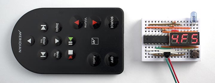
The IR Remote Control Tool displaying the code for a key on a hi-fi system remote.
I designed it to help with building a controller to switch devices remotely using an off-the-shelf remote control, such as switching lights or controlling a robot. It will also be useful if you're trying to automate the control of an existing domestic device using its infrared remote control codes, or as the basis for a learning remote control.
Operation
The IR Remote Control Tool works as follows. When you first switch it on it displays "---". If you point a remote control at it, and press a key, it will display the button's code in hexadecimal on the three-digit display.
If you press the button on the IR Remote Control Tool it will transmit the currently displayed code to the IR LED, so you can test the code with a piece of equipment that understands the IR codes.
The receive and transmit routines used in the IR Remote Control Tool are designed to be portable, so you can reuse them in other projects that need to receive or transmit IR codes.
RC-5 remote control protocol
This version of the IR Remote Control Tool decodes RC-5 format remote control codes [1]. This standard, originally developed by the consumer electronics firm Philips, is widely used by other manufacturers, especially in Europe.
The data is encoded using bi-phase encoding, also known as Manchester coding. All bits have a length of 1.778ms. A zero is represented as half a bit of carrier followed by half a bit of silence, and a one is half a bit of silence followed by half a bit of carrier:
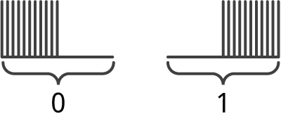
The half bit of carrier consists of 32 cycles at 36kHz. The pulses usually have a mark/space ratio of 1:4, to reduce the current consumption:

Each code sequence consists of 14 bits: two ones, followed by a toggle bit, followed by a 5-bit address and a 6-bit command; for example:
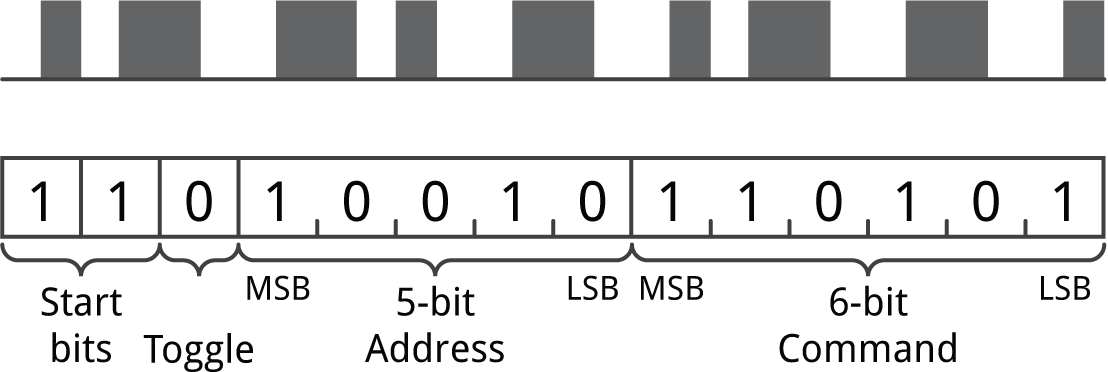
The Address identifies the piece of equipment being controlled, and the Command indicates which key was pressed. If the same key is pressed repeatedly, the toggle bit changes for each repeat of the code. If a key is held down, that key's code is sent repeatedly, once every 114ms, without changing the toggle bit.
Because the code sequence has a transition in the middle of every bit it's very tolerant of timing variations, and it should work fine with code running on an Atmel processor using its internal clock, without the need for a crystal.
The circuit
The circuit is based on an ATtiny84 and a 0.28" three-digit common anode seven-segment LED display bought on eBay. I used a 38kHz infrared receiver module available from Sparkfun [2], or from HobbyTronics in the UK [3], and it has a wide enough pass band to work with the 36kHz carrier frequency used by RC-5 [4]. For the transmitter I used an infrared LED salvaged from an old remote control, although any IR LED should work. While testing the circuit I substituted a standard red LED so I could check that the output was working.
Seven of the I/O pins from PORT A are used to drive the segments, and three of the I/O pins on PORT B are used to drive the digits. The remaining pin, PA0, receives the input from the IR receiver module. Because of the shortage of pins, three of the I/O lines are used for two functions. The I/O pin used to drive the rightmost display digit doubles as a driver for the decimal point, since the decimal point is not needed on the third digit. PA6 doubles as the driver for the IR LED. Finally, PA0 is also used to detect the Send button.
Here's the circuit, roughly reflecting the way it was laid out on the breadboard:
The circuit of the IR Remote Control Tool, based on an ATtiny84.
Here's a picture of the circuit on the breadboard with the display removed:
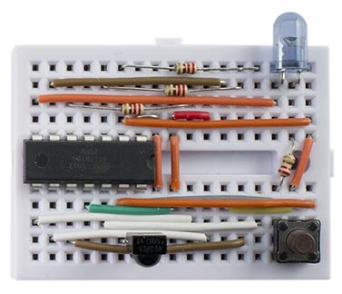
The IR Remote Control Tool showing the wiring under the display.
Multiplexing the display
As in several of my previous projects, the display is generated under interrupt, using the contents of the array Buffer[]. For example, to display "ABC" execute:
Buffer[0]=0xA; Buffer[1]=0xB; Buffer[2]=0xC;
The program uses Timer/Counter1 to generate an interrupt at 250Hz, which is used to multiplex the display. To make it easier to wire up the circuit on the breadboard I connected the segments to arbitrary pins on Port A. The array Segments[] specifies how they are wired, and the routine ReorderBits() then reorders the bits in the segment definitions to account for this:
void ReorderBits() {
  char segs, newsegs;
  for (int i=0; i<charArrayLen; i++) {
    segs = charArray[i];
    newsegs = 0;
    for (int i=0; i<7; i++) {
      newsegs = newsegs | ((segs & 1)<<Segments[i]);
      segs = segs >> 1;
    }
    charArray[i]=newsegs;
  }
}
IR receiver
The IR receiver routine, ReadRC5(), waits until it has received an RC-5 code, and returns it as a 14-bit value.
The infrared receiver module generates a high-level output when there's no carrier, and a low level on each carrier pulse. ReadRC5() first waits for the input to go low, indicating the middle of the first start bit.
For each bit it waits for 1334 microseconds, equivalent to 3/4 of a bit length, to get to the middle of the first half of the next bit, and shifts the level into the lowest bit of a variable rccode. It then waits for the next level change, which occurs in the middle of each bit.
After 14 bits have been shifted into rccode, bit 13 should be a '1' corresponding to the first start bit, and the value of rccode is returned:
int ReadRC5 () {
  int state, start, rccode = 0;
  while (digitalRead(IRin) == HIGH);
  state = 1;
  do {
    rccode = (rccode << 1) | state;
    // Wait 3/4 bit
    start = TCNT1;
    while (microsecs(start) < 1334);
    if (rccode & 0x2000) return rccode & 0x0FFF;
    state = digitalRead(IRin);
    // Wait for mid-bit transition
    start = TCNT1;
    do {
      if (microsecs(start) > 1718) return 0;  // Bottle out
    } while (digitalRead(IRin) == state);
  } while (1);
}
If the wait for a mid-bit transition takes longer than one bit width, 1718µs, the routine returns 0 to indicate that an error has occurred, such as an unrecognised IR code format.
The routine ReadRC5() uses the Timer/Counter1 counter to do the microsecond timing, since this is already running to do the display multiplexing:
int microsecs (int start) {
  int diff = TCNT1 - start;
  if (diff < 0) diff = diff + 5000;
  return diff;
}
If you are using ReadRC5() in another application you could provide an alternative timer, or use the Arduino library's micros() function. The routine returns the 12 bits received; you may want to mask off the toggle bit to leave just the address and command.
IR transmitter
The IR transmitter SendRC5() transmits a code in RC-5 format. It uses Timer/Counter1 in Fast PWM mode to generate the 36kHz carrier, by setting a prescaler of 1 and a TOP value of 221, and the output to OCR1 is inverted. To generate a half-bit gap it sets OCR1A to TOP, which generates a continuous low output on OCR1. To generate a stream of pulses with a 1/4 mark-space ratio it sets OCR1A to 165.
For each half bit the routine counts 32 pulse times. It counts each pulse by waiting for the overflow bit in register TIFR1. The routine continues until all 14 bits have been output:
void SendRC5 (int code) {
  int nextbit;
  code = code | 0x3000;  // Ensure there are two start bits
  TCNT1 = 0;             // Start counting from 0
  for (int b=0; b<14; b++) {
    nextbit = code>>(13-b) & 1;
    for (char i=0; i<2; i++) {
      if (nextbit) OCR1A = top; else OCR1A = match;
      // Wait for 32 Timer/Counter1 overflows
      for (int c=0; c<32; c++) {
        while ((TIFR1 & 1) == 0);
        TIFR1 = 1;
      }
      nextbit = !nextbit;
    }
  }
}
If you are using this routine in another application you could equally well use an 8-bit timer to generate the carrier pulses.
Main program
The main loop of the IR Remote Control Tool displays "---" and calls ReadRC5().
If this returns with an RC-5 code, the bottom 11 bits (excluding the start or toggle bits) are displayed in hexadecimal. Also, if the toggle bit is '1' the decimal point is illuminated.
If the button is pressed ReadRC5() returns 0, and the program outputs the last code to the IR LED. It then waits for another code to be received:
void loop() {
  int rccode, code;
  // Display mode
  rccode = 0;
  do {
    SetupDisplay();
    do {
      if (rccode) DisplayHex(rccode & 0x7ff); else Display(Dash);
      if (rccode & 0x800) dp = 0; else dp=-1;
      code = ReadRC5();
      if (code) rccode = code;
    } while (code != 0);
    // Pressed button - send IR code
    TIMSK1 = 0<<OCIE1A;    // Disable compare match interrupt
    for (int d=0; d<3; d++) digitalWrite(Digits[d], LOW);
    SetupPCM();
    pinMode(IRout, OUTPUT);
    SendRC5(rccode);
    // Wait for button release
    while (digitalRead(Button) == LOW);
  } while (1);
}
Compiling the program
I compiled the program using Spence Konde's ATTiny Core [5]. Choose the ATtiny24/44/84 option under the ATtinyCore heading on the Board menu. Then choose Clockwise, ATTiny84, 8 MHz (internal), B.O.D. Disabled, LTO Disabled from the subsequent menus. If necessary choose Burn Bootloader to set the fuses appropriately. Then upload the program using ISP (in-system programming); I used Sparkfun's Tiny AVR Programmer Board; see ATtiny-Based Beginner's Kit.
Here's the whole program for the IR Remote Control Tool: IR Remote Control Tool Program.
Other remote control formats
For information about adapting the IR Remote Control Tool to work with the NEC format, widely used in remote controls from the Far East such as the one available from Adafruit [6], see IR Remote Control Tool (NEC).
Addenda
20th March 2015: Tidied up the code a bit.
9th February 2018: Updated the description to use Spence Konde's ATTiny Core, and made minor updates to the program to avoid compiler warnings.
- ^ Data Formats for IR Remote Control by Vishay Semiconductors.
- ^ IR Receiver Diode - TSOP38238 on SparkFun.
- ^ Infra Red Receiver Module on HobbyTronics.
- ^ I also tested the circuit with an AX-1838HS infrared receiver module, included in some Arduino kits.
- ^ ATTinyCore on GitHub.
- ^ Mini Remote Control on Adafruit.
blog comments powered by Disqus