Scrolling Text Display PCB
16th December 2024
This is an extended version of my scrolling text display based on four 8x8 LED dot-matrix displays. You can edit it using a keyboard, and it's controlled by an ATtiny85:
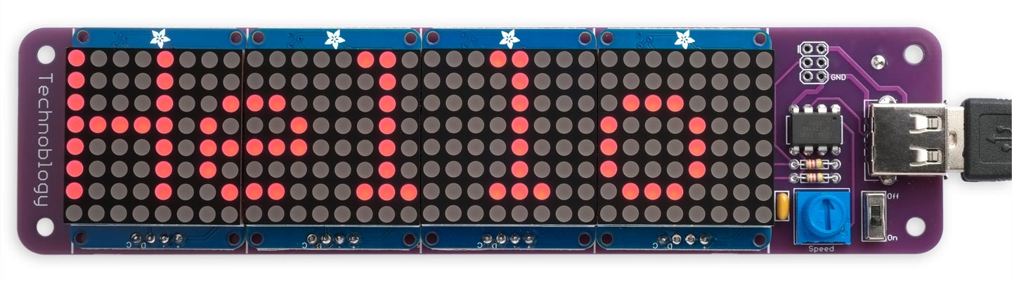
The PCB version of the Scrolling Text Display, based on an ATtiny85.
The earlier version was built on a breadboard, and though it worked perfectly, it wasn't very robust, and components tended to fall off if you dropped it. I've therefore designed a PCB for the circuit, and in the process made a few improvements.
I've put a lot of thought into designing this project so that it can be built by a parent or teenager with basic soldering skills. Using display modules that are available pre-assembled allows it to use through-hole components throughout, and so should be straightforward to assemble.
Introduction
I originally designed the Scrolling Text Display for the seven-year-old son of a friend, so he could make displays like the ones found on buses and trains. However, the uses he's found for it have greatly exceeded my expectations. It forms the basis for stories and plays, and is incorporated into other projects, such as a vending machine built from a cardboard box.
I've therefore been prompted to think of ways of extending these creative play opportunities, and this version of the software incorporates several improvements:
- It includes 26 picture symbols, on the keys Ctrl-a to Ctrl-z. Most of them start with the corresponding key; for example a = ant, b = boy, c = cat, d = dog, etc.
- You can replace any of the predefined pictures with your own pictures, using a simple bitmap editor; these could be logos, smileys, codes, or pictures to incorporate in stories.
- The Alt key displays any character in reverse video (including the picture symbols).
- The NumLock key gives the version number of the firmware.
- Pressing the ScrollLock key in Display mode resets the user-defined characters to their defaults. On most keyboards you have to hold down the Fn key to get this, making it hard to type it by mistake.
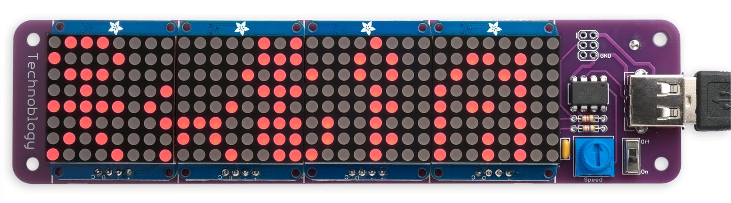
Some of the default user-definable characters: boy, dog, cat, key, and house.
Instructions
When you first switch on the Scrolling Text Display the current message scrolls along the display, whether or not there is a keyboard connected, so you can use it as a fixed message display.
Entering a message
To enter a message press Esc at any time to go into editing mode. You can then edit starting at the end of the existing message, or press Tab to clear the message and enter a new message.
While you're entering the message the last few characters are shown on the display, and you can press Backspace to delete back to correct mistakes.
Entering reverse-video characters
Hold down Alt while typing any key to enter the character in reverse-video.
Entering user-defined characters
Hold down Ctrl while typing one of the letters a to z to enter a user-defined character. These are initially defined to be pictures, such as ant, boy, cat, dog, etc. The letters Ctrl-v to Ctrl-z allow you to draw trains and carriages.
Designing your own characters
To design your own character, replacing one of the predefined characters, poceed as follows:
- While holding down Ctrl and Shift, type the letter a to z that you want to define.
- Then for each pixel in the 6x8 character, starting at top left, press '.' to draw a dot, or'/' or space to draw a space.
- The first six key presses define the top row, the next six key presses the second row, and so on for all eight rows.
- Press Backspace to delete mistakes.
When you've finished defining the character press Esc to go back to Edit mode, or Return to go to Display mode.
Displaying the message
When you've entered a message you can press Enter to go to Display mode, and the whole message will start scrolling repeatedly across the display. A five-space gap is inserted between the end of one presentation and the start of the next. While the message is scrolling you can adjust the speed using the potentiometer.
Resetting the user-defined characters
To reset the user-defined characters to their defaults press the ScrollLock key in Display mode.
Warning: You will lose any user-defined characters you have created.
Sourcing the displays
I've found three possible sources for displays compatible with this PCB:
Keyestudio KS0336
I originally designed the PCB is designed for use with four low-cost 1.2" (32mm) 8x8 dot matrix displays with an HT16K33 I2C driver, available from Keyestudio [1]. They are sold in sets of three, so you'll need two sets!
One disadvantage of the Keyestudio displays is that they are supplied with right-angle header pins already attached, and you'll need to remove these to mount the displays flat on the PCB. The best approach I've found is to clip off the right-angle header pins, gently lever off the plastic connecting strip, unsolder the pins one at a time to remove them, and then fit 4-way straight header pins in their place.
After building a prototype with four Keyestudio displays I ordered a second set of four displays, and was puzzled by the fact that the circuit didn't work, and if I hadn't quickly removed the power the displays would have been damaged. It turns out that Keyestudio have recently updated their display module with the VCC and GND connections reversed! I can't imagine what thinking led to this decision, but it forced me to make a second version of the PCB with solder links so you can adapt it to the type of module you've received. For safety the links are initially unconnected, and you have to add one solder bridge in each of the GND and VCC positions to connect the power correctly to the displays; see below. Note that all four modules must be the same type.
Adafruit 1049/1050
Adafruit make an identical 1.2" display that will also fit the PCB; it's available in a range of colours, but I recommend using red [2] or yellow [3] for the best battery life. For their latest version of this display Adafruit have added Stemma QT connectors, which are redundant for this application.
AliExpress
There are several suppliers on AliExpress selling what look like copies of the Adafruit displays [4]. These should also be suitable, and again I would keep to red or yellow to get the best battery life.
The circuit
The circuit is essentially identical to the breadboard version:
Circuit of the Scrolling Text Display PCB.
The displays
The key components in the Scrolling Text Display are the display modules. Each display incorporates an HT16K33 driver chip which drives the eight rows and eight columns of the LEDs, and allows you to control the display via an I2C interface. This is what allows the whole project to be controlled by just an 8-pin processor, the ATtiny85, and makes it easy to build the project without needing surface-mount soldering.
I2C Addresses
Three address solder links allow you to choose one of eight I2C addresses for each display, allowing you to drive up to eight displays simultaneously. The Keyestation modules have got the labels for A1 and A2 swapped around on the PCB, so the addresses you get with the eight possible PCB link settings are as follows:
| A2 | A1 | A0 | Address |
| 0x70 (112) | |||
| X | 0x71 (113) | ||
| X | 0x74 (116) | ||
| X | X | 0x75 (117) | |
| X | 0x72 (114) | ||
| X | X | 0x73 (115) | |
| X | X | 0x76 (118) | |
| X | X | X | 0x77 (119) |
You can use any addresses for the four displays, provided they're different. The array Addresses[] specifies the sequence, from left to right; for example:
int Addresses[] = {112, 113, 116, 117};
The Adafruit displays have the solder links correctly labelled.
Potentiometer
The potentiometer should be a 50kΩ or 100kΩ through-hole Cermet-style trimmer potentiometer. A suitable 50kΩ breadboard-compatible trimmer is available from The Pi Hut in the UK [5]. Alternatively they are available from AliExpress [6]. These potentiometers use two alternative pin layouts, and the PCB is designed to work with either.
Keyboard
The keyboard should be terminated in a USB-A plug, but include support for the older PS/2 interface. The one I used is the 220 x 118mm MC Saite MC-8017 Miniature PS/2 and USB keyboard, available from Adafruit [7]:
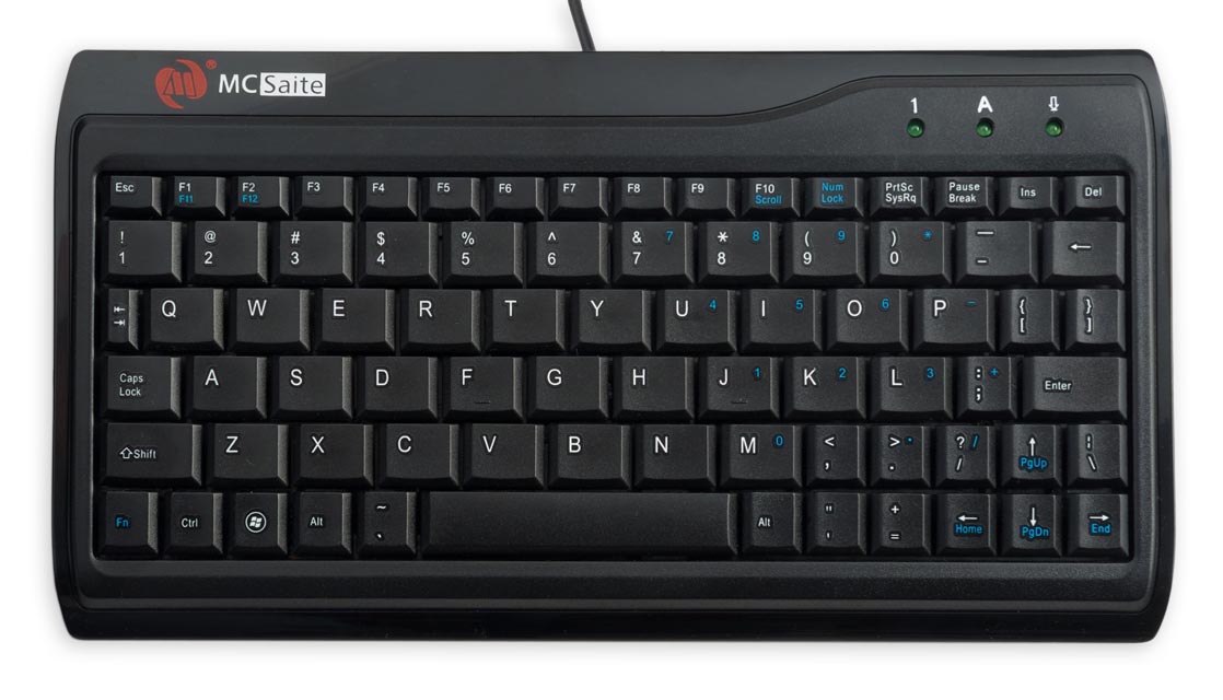
MC Saite MC-8017 Miniature PS/2 and USB keyboard.
I've tested the project with a slightly larger low-cost 284 x 122mm Slim Chiclet Keyboard [8], which also works fine.
Power
The Scrolling Text Display uses three 1.5V AAA batteries which mount onto the back of the PCB, and act as a stand for viewing the display:
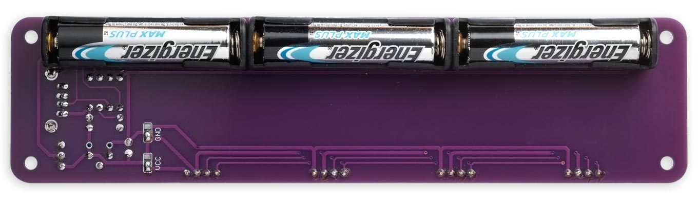
Back view of the Scrolling Text Display.
Here's the full parts list (click to expand):
► Parts list
Construction
I designed a PCB in Eagle and sent it to JLCPCB for production. There's a link at the end of the article if you want to make yourself some boards.
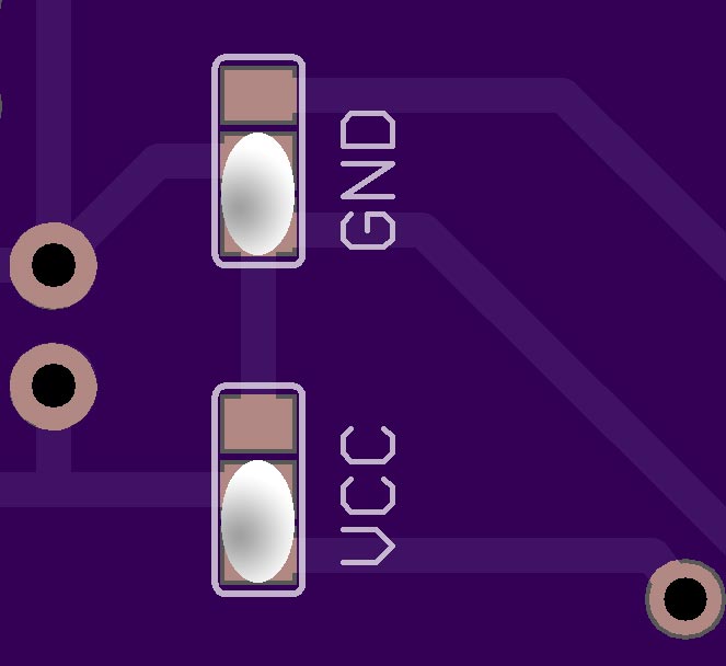
Solder bridges
Before starting, make solder bridges on the VCC and GND solder links on the reverse of the board according to the order of the VCC and GND pins on the display modules you are using:
 |
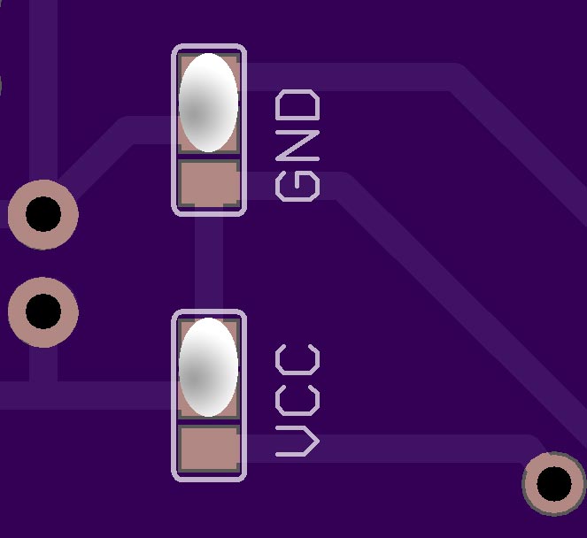 |
| VCC rightmost pin on display modules. Adafruit and old Keyestudio displays. |
GND rightmost pin on display modules. New Keyestudio displays. |
Display module spacing
The PCB is designed to space the display modules exactly to give a seamless display, which was not possible on the breadboard version. However, the Keyestudio boards are a fraction of a millimetre wider than the displays, so you may need to file down the boards slightly to get them to fit perfectly.
Recommended assembly sequence
Because some of the components block access to other components I recommend assembling the board in the following sequence:
- If you're using the Adafruit display modules you first need to solder the displays onto the boards. The displays must be fitted with the correct orientation or they won't work; check Adafruit's tutorial for details [9].
- Solder the ATtiny85, resistors, capacitor, potentiometer, USB socket, and on/off switch to the front of the board.
- Solder the battery holders to the reverse of the board, and clip the leads as close to the PCB as possible so they won't touch the backs of the dot matrix display modules. Most battery holders use steel leads, so don't use your best wire cutters as they may make dents in the jaws.
- Finally solder the displays to the front of the board, remembering to set the address link on the back of each display before doing this. I recommend attaching the displays to the PCB with double-sided self-adhesive pads before soldering the header pins.
The program
For details of the main features of the program see the original article: Scrolling Text Display - The Program. However, for the PCB version I've added a couple of features:
- If you type a character with the Alt key held down, the character is displayed as reverse video.
- The keys Ctrl-a to Ctrl-z display user-defined characters.
The codes used for these additional characters are as follows:
- User-defined characters: 0 to 25.
- Normal printing characters: 32 (space) to 127 (block).
- Inverse-video user-defined characters: 128 to 153.
- Inverse-video printing characters: 160 to 255.
A link to the updated version of the program is given below; it will work with the original breadboard version of the circuit too.
Uploading the program
To upload the program to the Scrolling Text Display PCB you'll need an ISP programmer. To make it easier to upload the program I've brought the programming connections to a standard 2x3 pin pad so you can connect to it with header pins, or a set of six pogo pins.
One option is Sparkfun's Tiny AVR Programmer Board [10]. Another option is Thomas Fischl's excellent USBasp programmer [11] , also widely available on eBay [12], and you can convert it to a pogo-pin programmer as follows:
Making a pogo-pin programmer
If you get a USBasp programmer with a 10-pin to 6-pin adapter for ISP programming you can replace the 6-pin socket with a set of six pogo pins [13] as described in the project Silver Dollar Game.
Compiling the program
Compile the program using Spence Konde's ATTiny Core [14]. Choose the ATtiny25/45/85 (No bootloader) option under the ATTinyCore heading on the Board menu. Then check that the subsequent options are set as follows (ignore any other options):
Chip: "ATtiny85"
Clock Source (Only set on bootload): "8 MHz (internal)"
B.O.D Level (Only set on bootload): "B.O.D. Enabled (2.7v)"
It's a good idea to set the Brown-out Detector (BOD) because it ensures that the processor stays reset when the battery voltage sinks to below a valid level; otherwise corruption of the EEPROM could occur.
Set Programmer to USBasp (ATTinyCore) (or whatever's appropriate for your programmer). Choose Burn Bootloader on the Tools menu to set the fuses appropriately. Then choose Upload on the Sketch menu to upload the program.
Resources
Here's the new version of the program: Scrolling Text Display PCB program.
Get the Eagle files for the PCB here: https://github.com/technoblogy/scrolling-text-display.
Or order them from OSH Park here: Scrolling Text Display.
Acknowledgements
Thanks to Chris Jordan for suggestions that have improved the original design.
- ^ Keyestudio 8*8 Matrix module on AliExpress.
- ^ Adafruit Small 1.2" 8x8 LED Matrix w/I2C Backpack - Red on Adafruit.
- ^ Adafruit Small 1.2" 8x8 LED Matrix w/I2C Backpack - Yellow on Adafruit.
- ^ 8X8 LED Dot Matrix Display Module I2C Interface on AliExpress.
- ^ Breadboard-friendly Trim Potentiometer on The Pi Hut.
- ^ Through Hole Trimmer Potentiometer on AliExpress.
- ^ Miniature PS/2 and USB keyboard on Adafruit.
- ^ Slim Chiclet Keyboard on Pimoroni.
- ^ Adafruit LED backpacks tutorial on Adafruit.
- ^ Tiny AVR Programmer on Sparkfun.
- ^ USBasp - USP programmer for Atmel AVE controllers on www.fischl.de.
- ^ USBASP Programmer Cable & Adapter on eBay.
- ^ Pogo pins "Needle Head" (10 pack) on Adafruit.
- ^ ATTinyCore on GitHub.
blog comments powered by Disqus